HP turbine vane airfoil profile
- Summary
- Abstract
- Description
- Claims
- Application Information
AI Technical Summary
Benefits of technology
Problems solved by technology
Method used
Image
Examples
Embodiment Construction
ment of the present invention; and
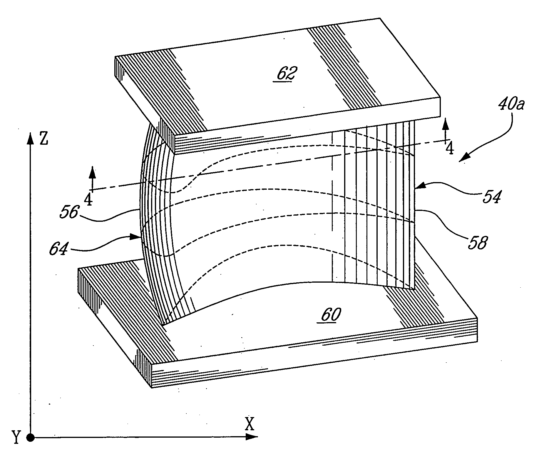
[0014]FIG. 4 is a cross sectional view taken along lines 4-4 of FIG. 3, showing a representative profile section of the airfoil portion of the vane.
DETAILED DESCRIPTION OF THE PREFERRED EMBODIMENTS
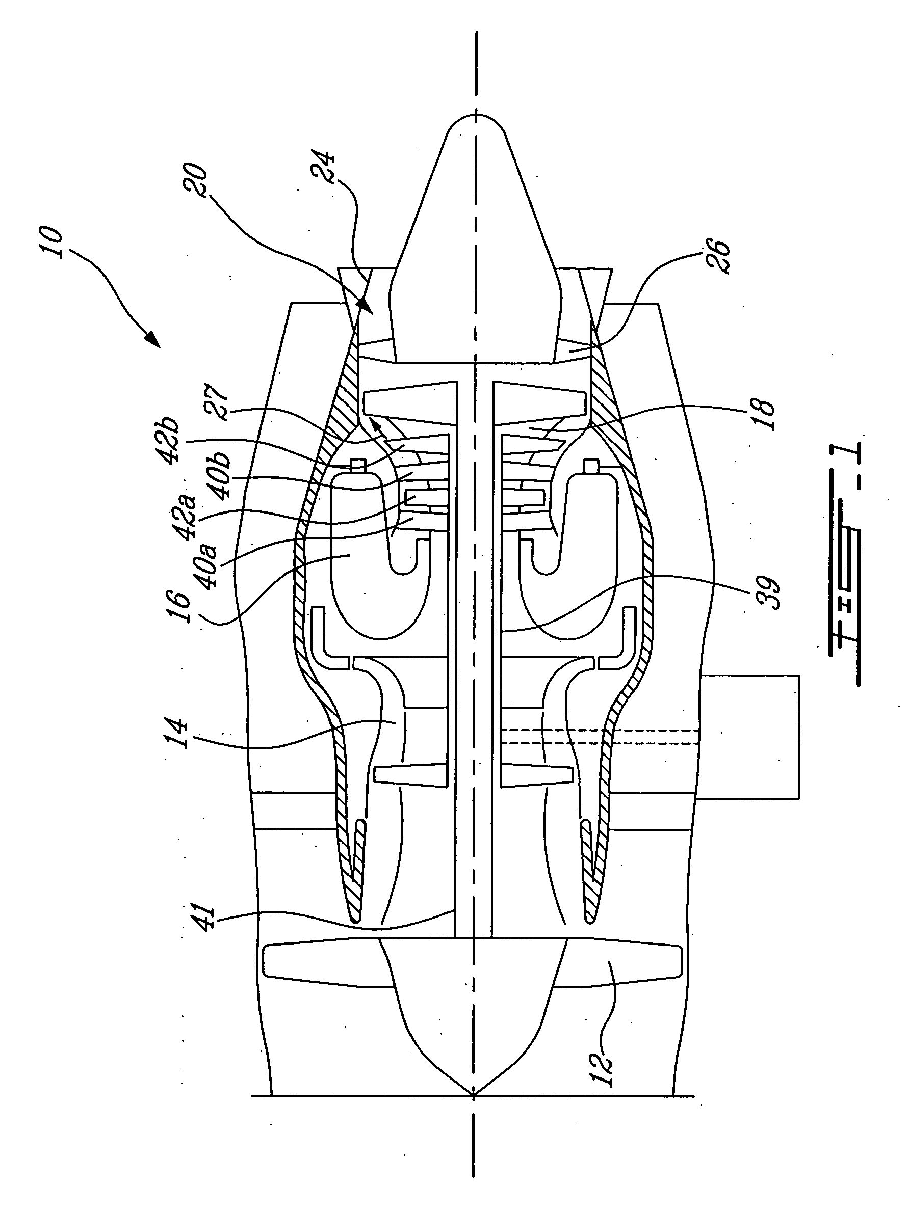
[0015]FIG. 1 illustrates a gas turbine engine 10 of a type preferably provided for use in subsonic flight, generally comprising in serial flow communication a fan 12 through which ambient air is propelled, a multistage compressor 14 for pressurizing the air, a combustor 16 in which the compressed air is mixed with fuel and ignited for generating an annular stream of hot combustion gases, and a turbine section 18 for extracting energy from the combustion gases to drive the fan, the compressor, and produce thrust.
[0016]The gas turbine engine 10 further includes a turbine exhaust duct 20 which is exemplified as including an annular core portion 22 and an annular outer portion 24 and a plurality of struts 26 circumferentially spaced apart, and radially extendi...
PUM
 Abstract
Description
Claims
Application Information
 - R&D
- Intellectual Property
- Life Sciences
- Materials
- Tech Scout
- Unparalleled Data Quality
- Higher Quality Content
- 60% Fewer Hallucinations
Browse by: Latest US Patents, China's latest patents, Technical Efficacy Thesaurus, Application Domain, Technology Topic, Popular Technical Reports.
© 2025 PatSnap. All rights reserved.Legal|Privacy policy|Modern Slavery Act Transparency Statement|Sitemap|About US| Contact US: help@patsnap.com


