Eureka AIR delivers breakthrough ideas for toughest innovation challenges, trusted by R&D personnel around the world.

Controlled evaporation, temperature control and packaging for optical inspection of biological samples

a biological sample and temperature control technology, applied in the field of microarrays, can solve the problems of evaporation of reaction solution, no effective mixing of analyte, fluid flow, etc., and achieve the effects of reducing reaction time, increasing the effective analyte concentration, and reducing volume of reaction solution

Inactive Publication Date: 2005-04-14
GONCHARKO MICHAEL +2
View PDF11 Cites 20 Cited by
  • Summary
  • Abstract
  • Description
  • Claims
  • Application Information

AI Technical Summary

Benefits of technology

Disclosed are improvements to open assay formats, wherein the volume of reaction solution is reduced in a controlled manner by evaporation during the assay, in order to increase the effective analyte concentration, and to induce evaporation-mediated stirring of the analyte solution, to thereby reduce reaction time required. The rate of evaporation must be controlled so as to avoid precipitation of salt or other assay constituents. Controlled evaporation induces convective fluid flow, and given that the flow field in specific geometries such as that of a hemispherical drop of analyte solution is known, a controlled rate of evaporation affords precise control over the flow rates in the drop and hence of the parallel fluid flow achieved near the substrate surface, where analyte and ligand make contact. A numerical estimate of the evaporation-mediated flow rate can be calculated as set forth below.
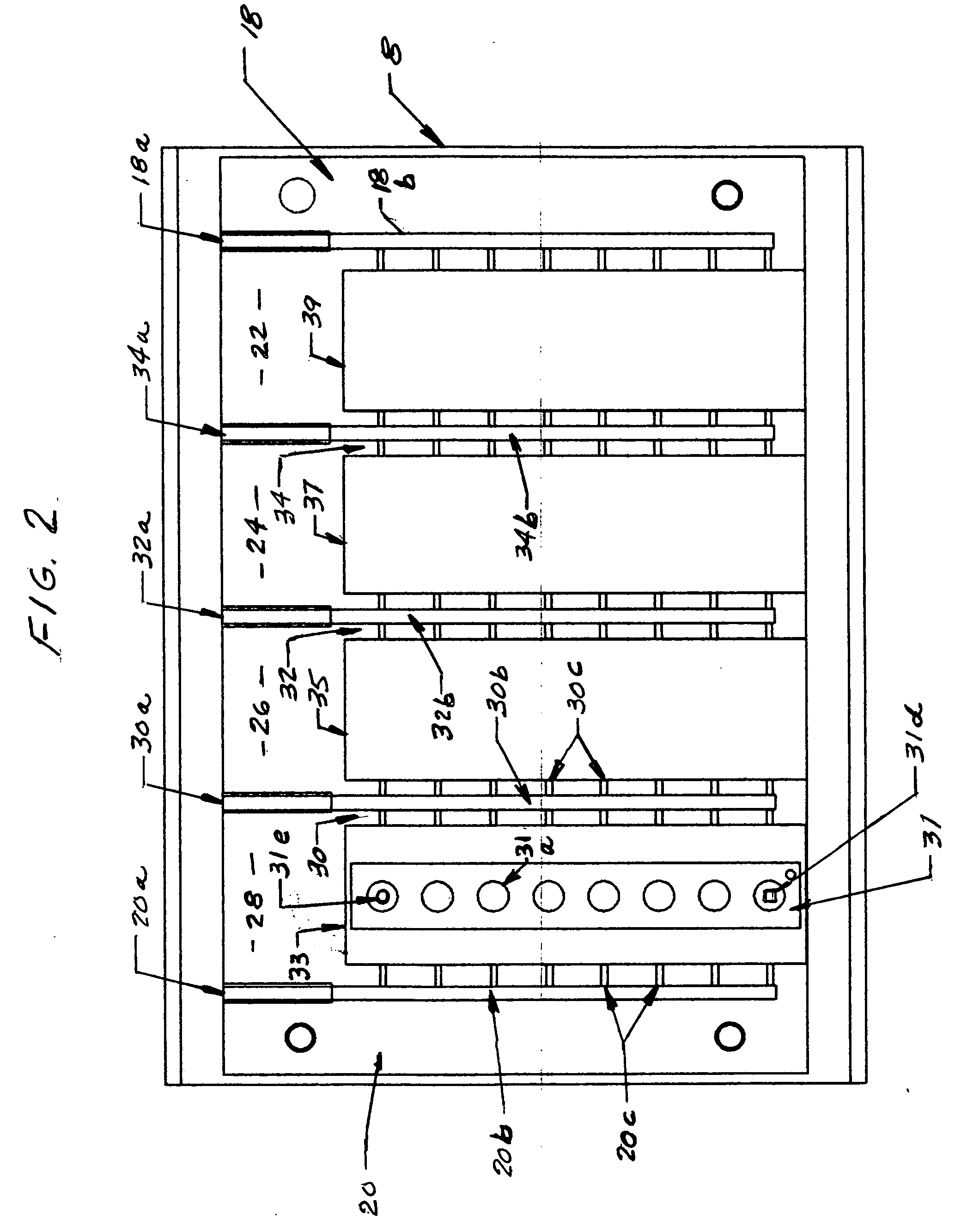
A number of designs can be employed to minimize temperature gradients in the oven. In one such design, heating elements are in place both above and below the slides, to minimize the vertical gradient. The slides in the chambers may be heated by convection (from the air flow), conduction (from a lower plate in the chamber which is heated) and radiation (from a heating element above the upper surface, which is darkened to generate black body radiation). To minimize heat sinking by way of metal attachment means, the plate beneath the chambers can be insulated from the metal supports on which it rests, by using washers and bolts made of an insulting material (preferably, nylon).
Following the reaction and reduction in solution volume by way of evaporation, it is desirable to enclose the solution so as to prevent further evaporation or contamination. One can use a transparent, optical tape, which is placed over the slide, in lieu of a coverslip. The use of tape minimizes the misalignment and slippage which commonly occurs during handling and viewing, when using conventional coverslips, and eliminates the need for re-alignment. The tape preferably includes a film layer (facing the viewer) and an adhesive layer (to adhere to the slide), and is designed such that the distortion of a bead array is not substantially greater than that experienced when applying a glass coverslip. The tape also should have minimal autoflourescence, so as to not generate excessive background signal.

Problems solved by technology

In hermetically sealed sandwich cells, there will be no fluid flow and no effective mixing of analyte during the assay.
Another disadvantage of sandwich cells is that fluidic access to the sample chamber requires disassembly of the chamber to create an open format, that is desirable, for example, for ease of pipetting.
In addition, in a closed format, high pressure is required to force fluid into the narrow gap, and such injection can be difficult to control and can generate leaks, which would be especially undesirable for assays requiring multiple steps, as leakage would occur at each washing step.
Open assay formats can, however, lead to evaporation of the reaction solution, which has generally been perceived as undesirable.
Coverslips are lightweight and thin and tend to move about during handling and viewing, and often break.

Method used


Image

  • Controlled evaporation, temperature control and packaging for optical inspection of biological samples
  • Controlled evaporation, temperature control and packaging for optical inspection of biological samples
  • Controlled evaporation, temperature control and packaging for optical inspection of biological samples

Examples


example

Assay Results Using Tape

The Corning tape was evaluated by comparing results obtained using a bead array of oligonucleotide probes hybridized with target oligonucleotides. The signal intensity in FIGS. 4A and 4B represent the label associated with the target oligonucleotide bound by probes displayed on beads within the array. Each cluster of beads in the array generates the signals shown by the larger bars in FIGS. 4A and 4B, the smaller bars in FIGS. 4A and 4B representing background.


PUM

PropertyMeasurementUnit
temperatureaaaaaaaaaa
volumeaaaaaaaaaa
humidityaaaaaaaaaa

Abstract

Controlling humidity at the surface of a solution containing analyte and ligand, e.g., for an assay, is disclosed, wherein the control of the humidity induces evaporative stirring in the solution to bring analyte and ligand into contact more quickly than when using diffusion. An oven which blows air in a controlled stream across slides, with wells containing reagent and analyte, is disclosed. Also disclosed is optical tape which can replace a conventional glass coverslip used for viewing of the reaction results.

Description

BACKGROUND Microarrays have been widely applied in proteomic, and particularly in genomic analysis. See, e.g., Ramsay, Nat. Biotechnol. 16, 40-44 (1998); P. Brown, D. Botstein, Nat. Genet. 21, 33-37 (1999); D. Duggan, M. Bittner, Y. Chen, P. Meltzer, J. M. Trent, Nat. Genet. 21, 10-14 (1999); R. Lipshutz, S. P. A. Fodor, T. R. Gingeras, D. J. Lockhart, Nat. Genet. 21, 20-24 (1999). A simple method of forming a microarray is to spot binding agents such as antibodies and oligonucleotides on planar substrates. These binding agents are then contacted with samples including complementary ligands (proteins or complementary oligonucleotides, as applicable) and permitted to bind or hybridize. The product of binding interaction or hybridization is then detected. Because either the identity of the binding agents or the complementary ligands are known, by tracing them in the array, the complementary oligonucleotides or proteins can be determined. This is an effective method for identification...

Claims


Application Information

Patent Timeline
Patent Type & Authority Applications(United States)
IPC IPC(8): B01B1/00B01D1/14B01L3/00B01L9/00C12M1/34C12Q1/68G01N1/31G01N1/40
CPCB01B1/005B01D1/14B01L3/50853B01L9/52G01N2001/4027B01L2300/041B01L2300/0636B01L2300/0822G01N1/312B01L2200/0678
Inventor GONCHARKO, MICHAELCHAU, CHIUFINAMORE, BETH ANN
Owner GONCHARKO MICHAEL
Why Eureka
Eureka Blog
Learn More