
Safety Accommodation Arrangement in LED Package/Secondary Lens Structure

Active Publication Date: 2008-11-06
IDEAL IND LIGHTING LLC
View PDF13 Cites 155 Cited by
  • Summary
  • Abstract
  • Description
  • Claims
  • Application Information

AI Technical Summary

Benefits of technology

[0012]An object of the invention is to provide an improved LED module which achieves the electrical product safety demanded by the marketplace.
[0014]Still another object of the invention is to provide an improved LED module which achieves such electrical product safety under conditions during which no lens remains place over each LED package.
[0016]The invention is LED apparatus which provides electrical safety by satisfying a set of stringent safety standards for the enclosures in which such LED apparatus are encased, and doing so in a cost-effective manner. The LED apparatus of this invention includes a mounting board having a plurality of LED packages thereon with a lens member over each LED package and a safety barrier positioned over the mounting board. The barrier has sufficient thickness for enclosure of electrical elements on the mounting board and includes a plurality of openings each sized to permit light from an LED package to pass therethrough and through a light-transmission portion of the lens member over such LED package to prevent finger-contact of electrical elements on the mounting board when the light-transmission portion is not present.

Problems solved by technology

Significant heat levels in such products can pose particular problems for lens-over-lens mounting and stability.
One potential problem is that temperature changes may cause thermal expansion and related alignment problems.
Protection against various environmental factors is also rendered difficult for LED general illumination products which necessarily utilize a large number of LEDs—sometimes plural LED modules with each module having many LED packages thereon.
The product safety of lighting fixtures creates an additional area of difficulty, and such fixtures are most often required to comply within standards put forward by organizations such as Underwriters Laboratories Inc.
Increased product safety can be costly to achieve, both in terms of the economic cost associated with providing safety as well as with the loss of lighting performance such as reduced optical efficiency.
For example, placing a fixture behind a sheet of glass to provide increased safety can result in an optical efficiency loss of up to 10%.
For LED-based lighting fixtures, the cost of the power supply is an important part of the overall fixture cost.
In particular, power supplies with a Class 2 power supply rating are limited to 100 watts at a maximum of 60 volts (30 volts if under wet conditions).
If power requirements for a lighting fixture are higher than the Class 2 limits, then multiple Class 2 power supplies are required (which can be costly) unless the more stringent safety standards which using a Class 1 supply brings about can be achieved.
It is assumed that under these circumstances, the polymeric secondary lenses will be destroyed in the fire, leaving the primary lenses exposed.

Method used


Image

  • Safety Accommodation Arrangement in LED Package/Secondary Lens Structure
  • Safety Accommodation Arrangement in LED Package/Secondary Lens Structure
  • Safety Accommodation Arrangement in LED Package/Secondary Lens Structure

Examples


Embodiment Construction

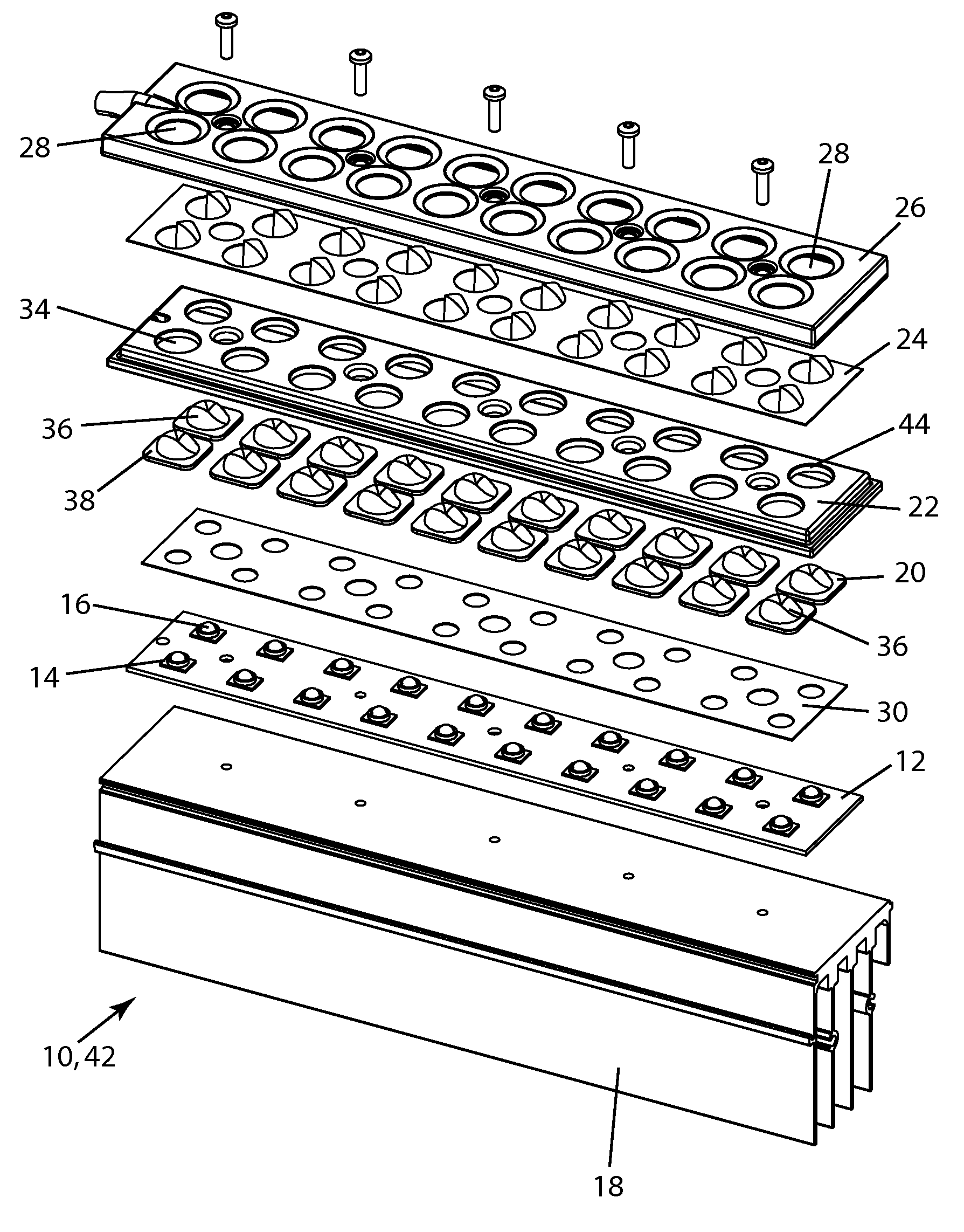
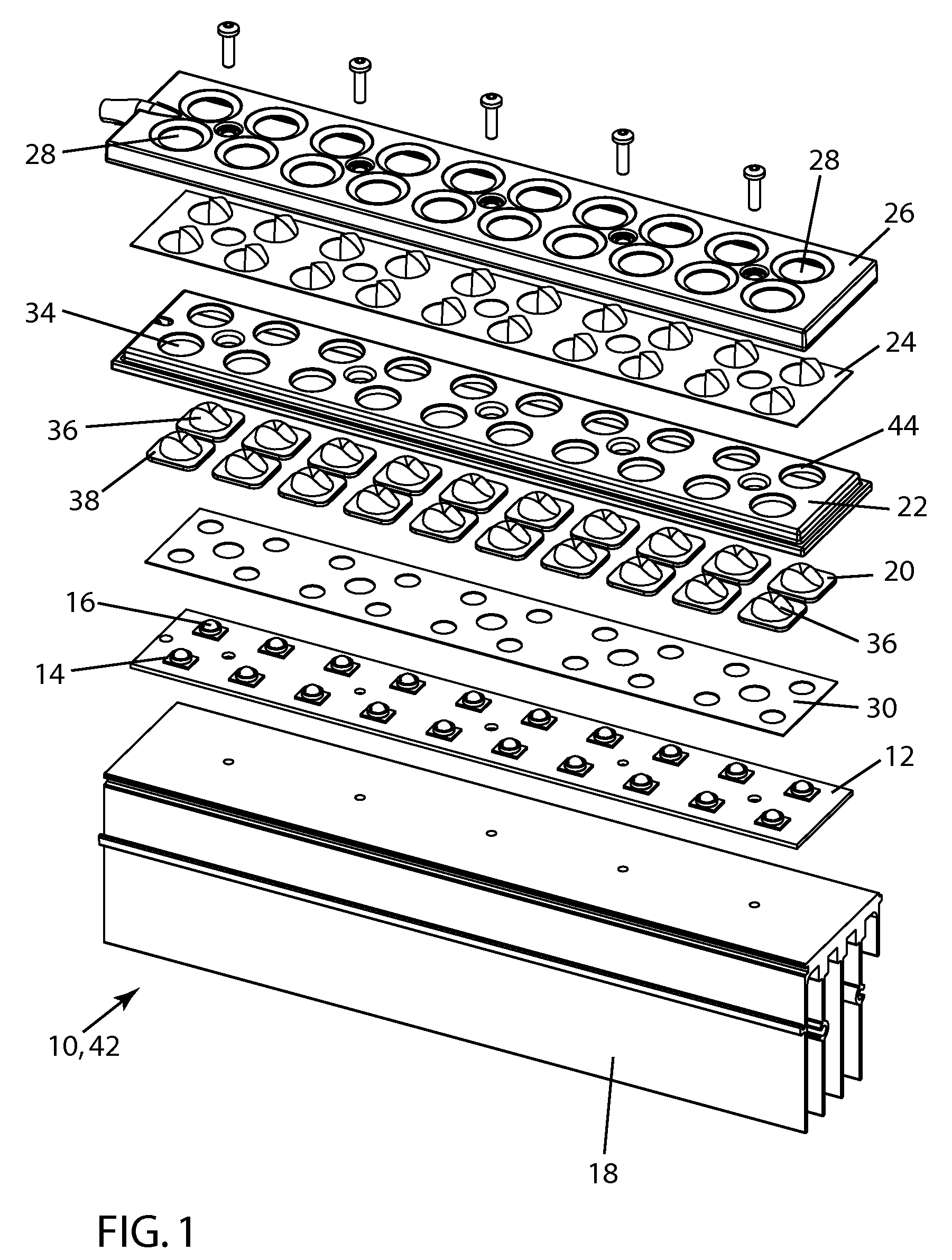
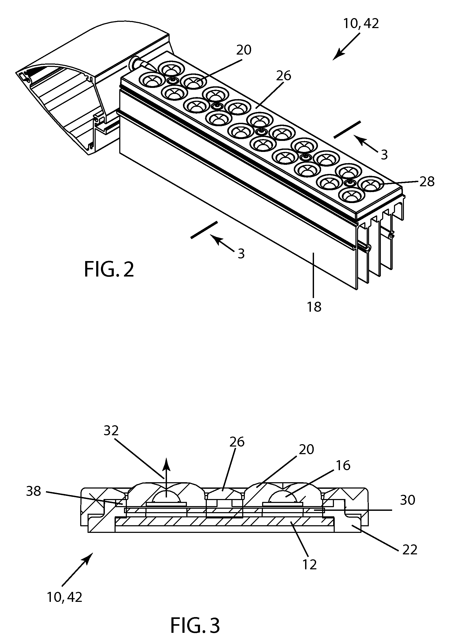
[0038]FIGS. 1-3 illustrate an LED apparatus 10 which includes a mounting board 12 with a plurality of LED packages 14 thereon. The LED packages include primary lenses 16. Secondary lens 20 are positioned over primary lenses 16, establishing light paths 32 therebetween. Mounting board 12 is connected to a heat sink 18 as shown in FIG. 1. Apparatus 10, having such plural LED packages mounted thereon, is also referred to as an LED module 42 as indicate din FIG. 1. One or more LED modules 42 are used as the light source for various inventive lighting fixtures. One example of such an inventive LED lighting 100 is shown in FIGS. 12A and 12B. LED apparatus 10 includes a resilient member 22 against secondary lenses 20 in positions other than in light path 32. Resilient member 22 is yieldingly constrains secondary lenses 20 and accommodates the movement of secondary lenses 20 caused by thermal expansion during operation, primarily by that of primary lenses 16 in the embodiment shown in FIG. ...


PUM


Abstract

An LED apparatus including (a) a mounting board, (b) a plurality of LED packages thereon, (c) a lens member over each LED package, and (d) a safety barrier positioned over the mounting board, the barrier having sufficient thickness for enclosure of electrical elements on the mounting board and including a plurality of openings each sized to permit light from an LED package to pass therethrough and through a light-transmission portion of the lens member over such LED package to prevent finger-contact of electrical elements on the mounting board when the light-transmission portion is not present.

Description

RELATED APPLICATION[0001]This is a continuation-in-part of patent application Ser. No. 11 / 744,807, filed on May 4, 2007 and entitled “Sealing and Thermal Accommodation Arrangement in LED Package / Secondary Lens Structure.”FIELD OF THE INVENTION[0002]The invention relates generally to the field of LED lighting systems and, more particularly, relates to configurations for LED modules in lighting fixtures.BACKGROUND OF THE INVENTION[0003]In the field of lighting, many different types of light sources have been developed. Recently, LED light sources involving multi-LED arrays, each with a large number of LED packages, have been developed as a means of bringing the many advantages of LED lighting—LED efficiency and long life—into the general illumination field. In particular, such LED light fixtures have been developed for use in outdoor settings, including by way of example lighting for parking lots, roadways, display areas and other large areas.[0004]LED fixtures in the prior art have c...

Claims


Application Information

Patent Timeline
IPC IPC(8): F21V5/00
CPCF21S2/005F21V5/007F21V5/08F21V15/01F21V25/00Y10S362/812F21V31/005F21W2131/103F21Y2101/02F21Y2105/001F21V25/12F21Y2105/10F21Y2115/10
Inventor WILCOX, KURT S.GUILLIEN, WAYNE P.
Owner IDEAL IND LIGHTING LLC
Learn More