
Self Contained Foam Dispenser

a dispenser and self-contained technology, applied in the direction of mixers, liquid/fluent solid measurement, containers, etc., can solve the problems of clogging flow passages, affecting the quality of foam, so as to reduce waste, reduce element replacement costs, and improve quality

Inactive Publication Date: 2008-11-06
P G UNITED STATES ISRAEL
View PDF66 Cites 35 Cited by
  • Summary
  • Abstract
  • Description
  • Claims
  • Application Information

AI Technical Summary

Benefits of technology

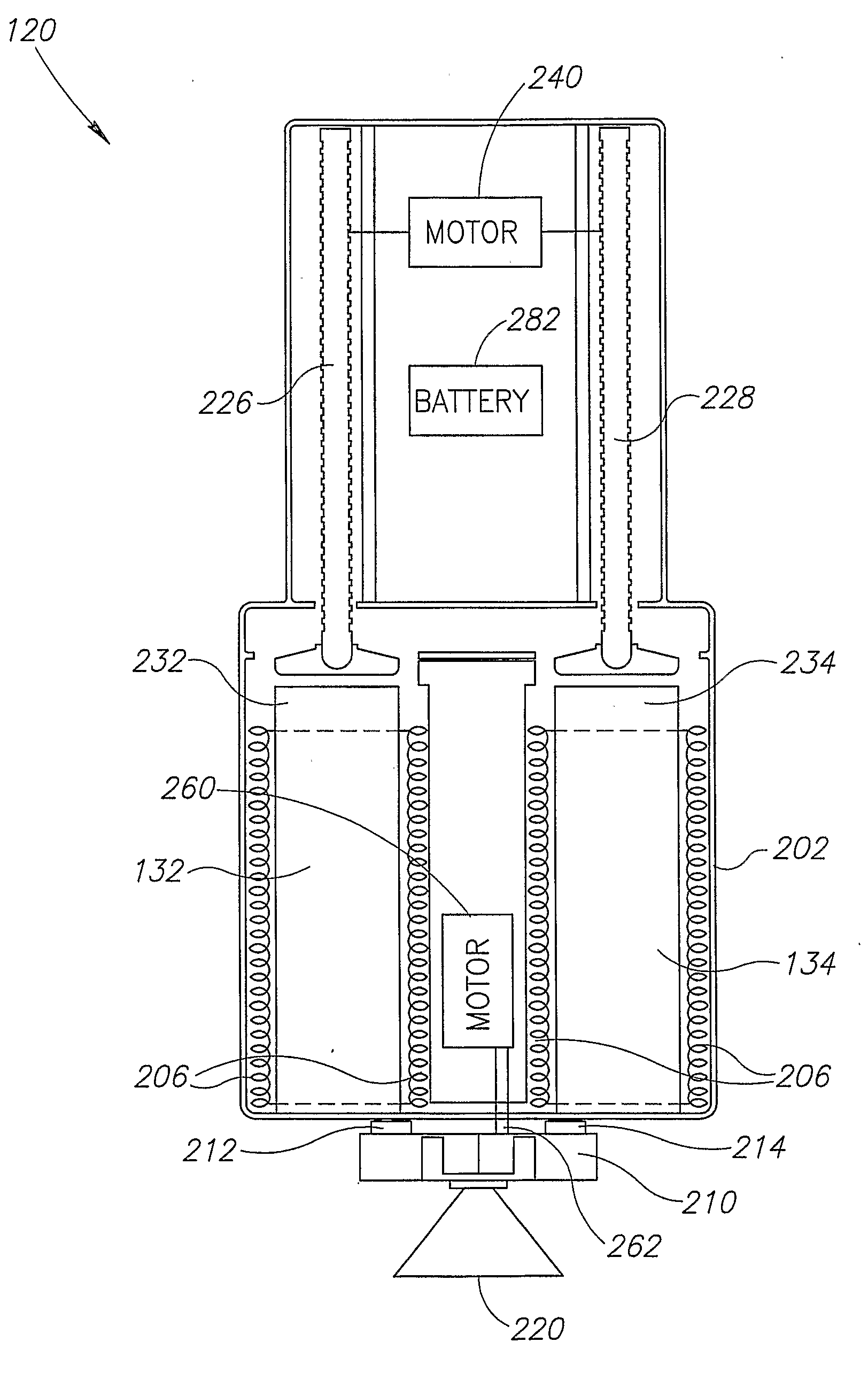
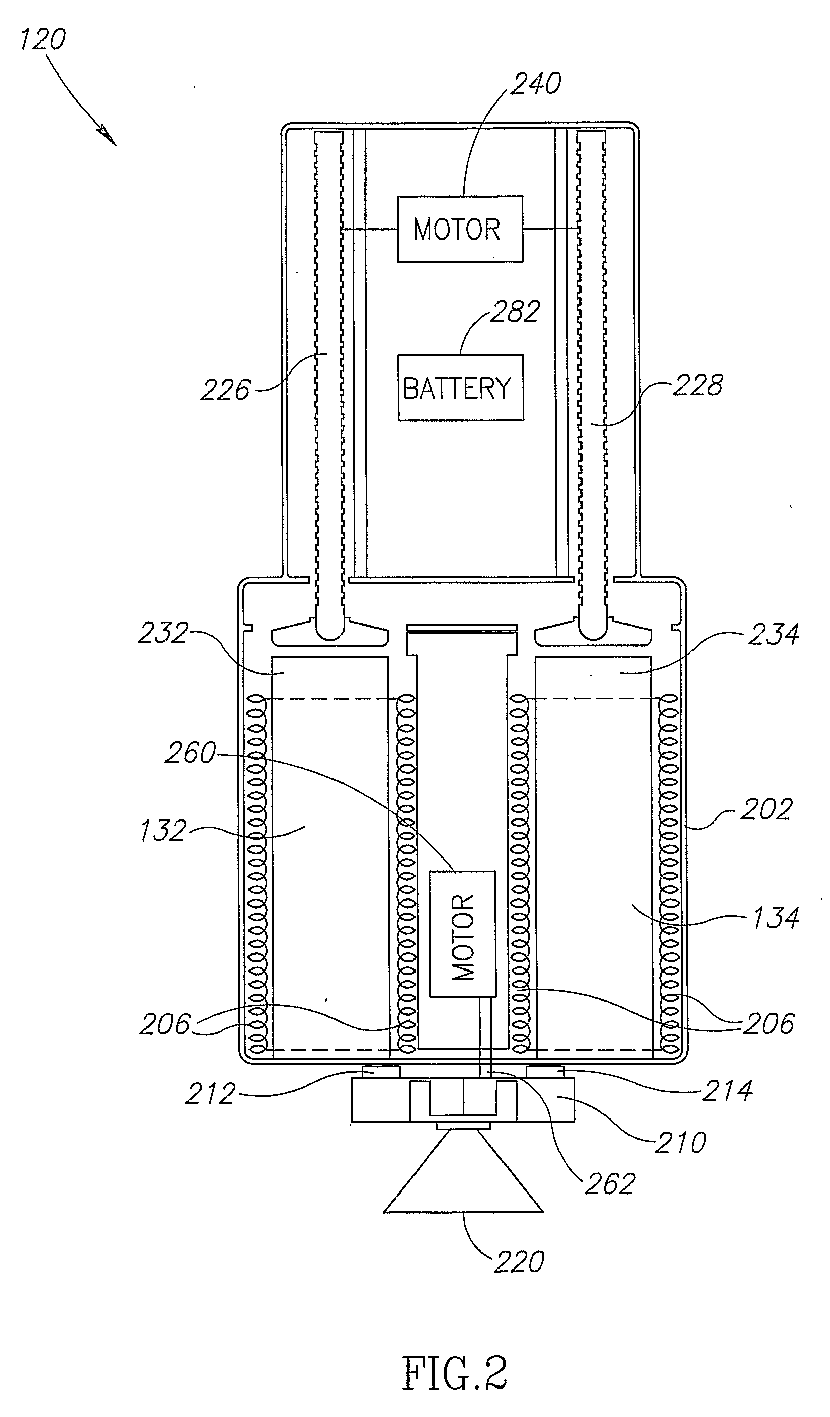
[0010]A general aspect of some embodiments of the invention relates to a self-contained foam dispensing device, i.e., a dispensing device having chemical containers mounted on or included in the device, which provides high quality foam mixing. The dispensing device optionally allows intermittent use in small amounts over a relatively long period, with reduced waste and / or reduced element replacement costs. Optionally, the compact dispensing device is hand-held, along with foam chemical containers.
[0011]An aspect of some embodiments of the invention relates to a self-contained dispensing device for generating foam, which includes at least one pump, or other flow generator, located between the chemical containers and a mixing chamber of the device. The pump between the chemical containers and the mixing chamber provides more accurate and / or efficient operation, than provided by pressure units for pushing chemicals out of their containers, located behind the containers. In addition, using a pump between the containers and the mixing chamber allows use of non-rigid containers such as plastic bags or elastic bags. Having the pump between the containers and the mixing chamber also allows for a more compact dispensing device and allows simpler replacement of the pump and the mixing chamber in cases of problems. In some embodiments of the invention, the pump is connected to a nozzle defining the mixing chamber.

Problems solved by technology

The above hand-held apparatus are generally inaccurate in the proportions of chemicals they mix and provide a low quality foam mix.
As foam materials harden within a short time, remnants of the foam may harden within the dispensing apparatus and clog flow passageways.
In addition, a delivery conduit is required in medical applications but not in packaging applications.

Method used


Image

  • Self Contained Foam Dispenser
  • Self Contained Foam Dispenser
  • Self Contained Foam Dispenser

Examples


Embodiment Construction

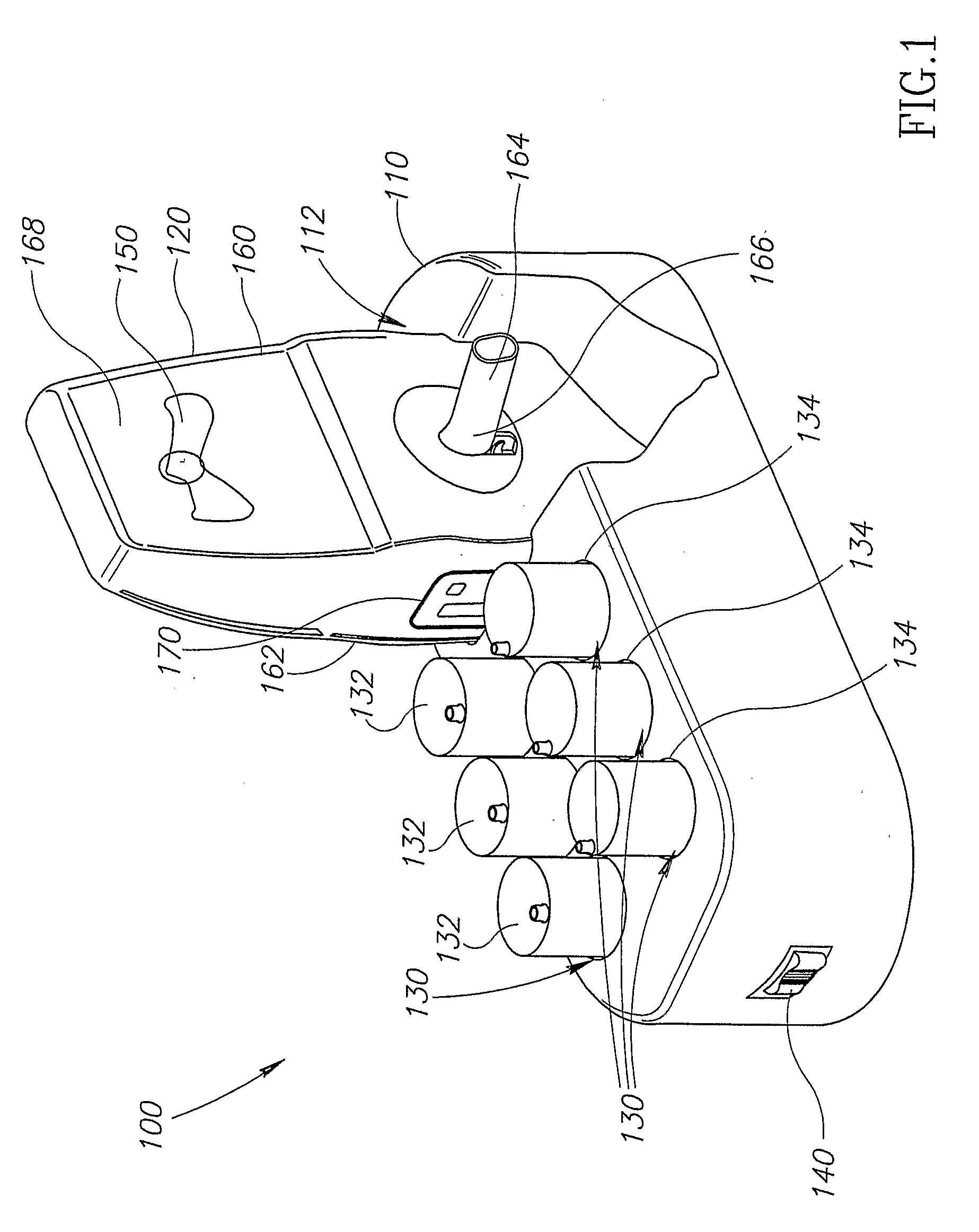
[0052]FIG. 1 is a schematic illustration of a foam generating and dispensing system 100, in accordance with an exemplary embodiment of the invention. System 100 comprises a base 110 which includes a recess 112 sized and shaped to receive a hand-held foam dispensing gun 120. Optionally, a battery (not shown) of gun 120 is charged when the gun is properly placed in recess 112. Base 110 optionally further includes a plurality of recesses 130 adapted to receive chemical containers, and heat the containers while they are in the recesses. In an exemplary embodiment of the invention, recesses 130 host containers 132 of a chemical A, e.g., and containers 134 of a chemical B. In an exemplary embodiment of the invention, chemical A comprises a polymeric isocyanate or a fluorocarbon, while chemical B comprises polyols, catalysts or flame retardants. It is noted, however, that system 100 is not limited to use with any specific chemicals and has advantages which are useful for mixing many chemic...


PUM

PropertyMeasurementUnit
pressureaaaaaaaaaa
volumeaaaaaaaaaa
weightaaaaaaaaaa

Abstract

A self-contained foam dispensing device includes a casing, a mixing chamber, a port adapted to receive one or more containers including a plurality of chemicals in a plurality of compartments and a flow generator adapted to induce flow of chemicals from the compartments toward a mixing chamber, the flow generator being located between the mixing chamber and the port. When the one or more containers are in the port the one or more containers move with movement of the casing.

Description

RELATED APPLICATIONS[0001]The present application claims the benefit under 35 U.S.C. 119(e) of U.S. provisional application 60 / 556,883, titled “Hand-Held Dispenser”, filed Mar. 29, 2004, the disclosure of which is incorporated herein by reference.FIELD OF THE INVENTION[0002]The present invention relates to foam dispensers and particularly to hand held foam dispensers.BACKGROUND OF THE INVENTION[0003]Foam materials are commonly used for packaging. The foam is generally generated by mixing two chemical components, which harden within about 10-30 seconds. In many cases, a foam dispensing gun is used to generate the foam at the packaging site. U.S. Pat. No. 4,262,848 to Chabria and U.S. Pat. No. 5,462,204 to Fiin, the disclosures of which are incorporated herein by reference, describe such guns which are connected through tubes to large containers including the chemicals used in forming the foam. The dispensing gun generally includes a pair of pumps which pump the chemicals out of the c...

Claims


Application Information

Patent Timeline
Patent Type & Authority Applications(United States)
IPC IPC(8): B67D5/52B65D88/54B01F5/02B67D7/06B01F13/00B01F15/02B29B7/74B65D35/22B67D7/70B67D7/76B67D7/78
CPCB01F5/0256B01F13/002B01F13/0023B01F13/0027B29B7/7452B01F15/0087B01F15/0201B01F15/0237B29B7/7447B01F15/0085B01F25/23B01F33/50114B01F33/50112B01F33/5011B01F35/522B01F35/513B01F35/71B01F35/7174
Inventor MALIK, MOSHELEVINNEVO, SHLOMO
Owner P G UNITED STATES ISRAEL
Learn More