
Thin-Film Laminate

a thin film, laminate technology, applied in the direction of conductive layers on insulating supports, identification means, instruments, etc., can solve the problems of difficult mechanical strength of laminate per se, reducing the visibility of images, and reducing the mechanical strength of laminates. , to achieve the effect of improving the mechanical strength of thin film laminates and improving the adhesion of each layer

Inactive Publication Date: 2008-10-30
SWISS REINSURANCE CO LTD +1
View PDF6 Cites 9 Cited by
  • Summary
  • Abstract
  • Description
  • Claims
  • Application Information

AI Technical Summary

Benefits of technology

The present invention provides a thin-film laminate that prevents the occurrence of interference reflection and interference fringes at the interface between a light-transparent base material and an antistatic layer, and the interface between the antistatic layer and the hardcoat layer. This is achieved by rendering the interfaces substantially absent. The thin-film laminate has improved mechanical strength, an excellent antireflection function, and visibility. The invention also provides a method for preparing a composition for an antistatic layer and a composition for a hardcoat layer that can form the laminate structure.

Problems solved by technology

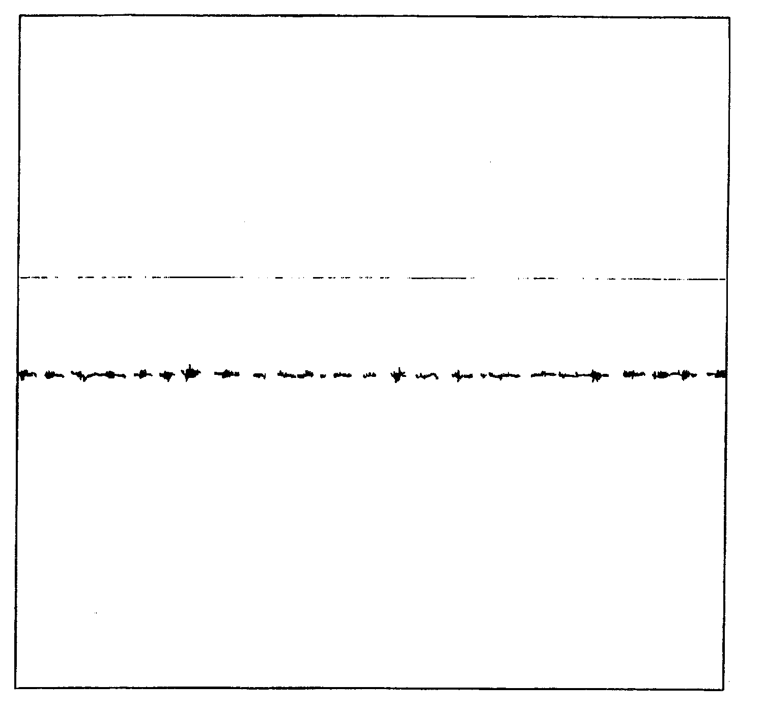
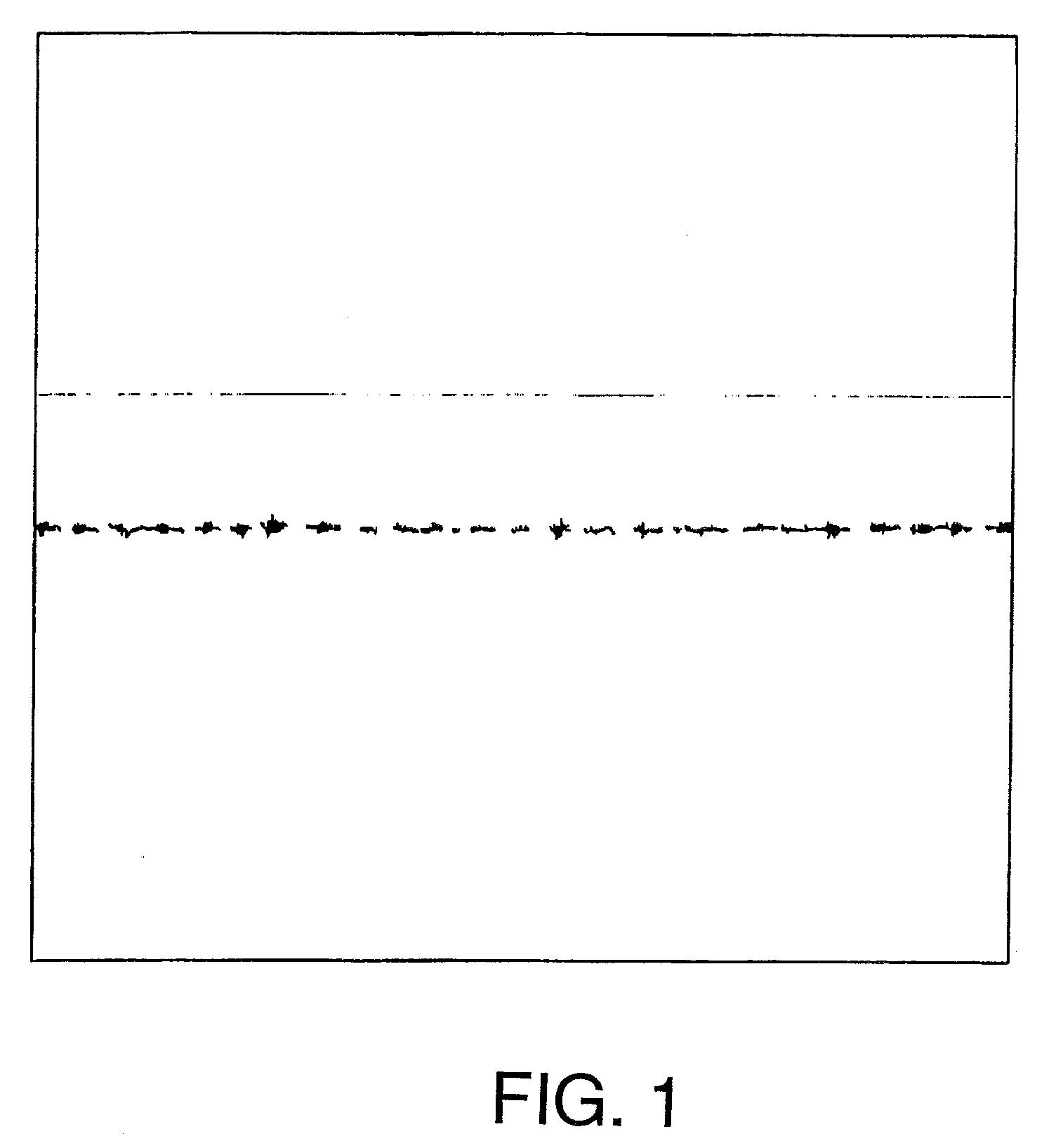
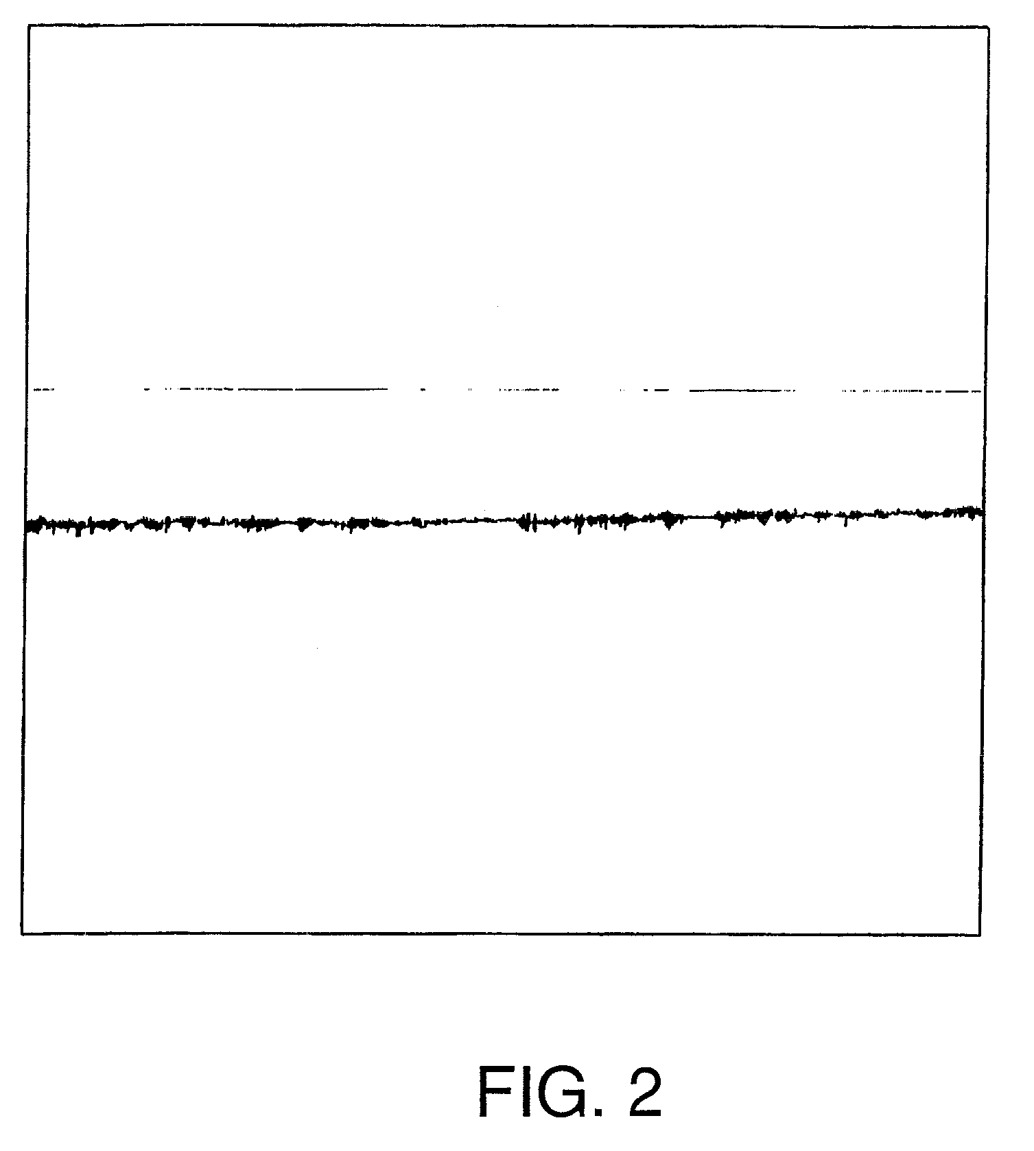
In an antireflective laminate comprising layers with a large refractive index difference stacked on top of each other, however, interface reflection and interference fringes often occur at the interface of the mutually superimposed layers.
In particular, when black is reproduced on an image display surface in a screen display device, the occurrence of interference fringes is significant, resulting in lowered visibility of the image.
Furthermore, it has been regarded that, when a layer having a very low refractive index (for example, less than 1.2) is stacked, the production of an antireflective laminate simultaneously having the adhesion to other layer(s) and the mechanical strength of the laminate per se is difficult.

Method used


Image

  • Thin-Film Laminate
  • Thin-Film Laminate
  • Thin-Film Laminate

Examples


example 1

[0104]A light-transparent base material (triacetylcellulose resin film with thickness of 80 μm (TF80UL, manufactured by Fuji Photo Film Co., Ltd.) was provided. Composition 1 for an antistatic layer was coated by a wound coating rod onto one side of the film. The coated film was held in a hot oven kept at a temperature of 70° C. for 30 sec to evaporate the solvent in the coating film. Thereafter, the coating film was cured by applying ultraviolet light to the coated film so that the integrated quantity of light was 98 mJ. Thus, a transparent antistatic layer was formed at a coverage of 0.7 g / cm2 (on a dry basis) to prepare an antistatic laminate. Thereafter, the composition for a hardcoat layer was coated, and the assembly was held in a hot oven kept at a temperature of 70° C. for 30 sec to evaporate the solvent in the coating film. Thereafter, the coating film was cured by applying ultraviolet light to the coating film so that the integrated quantity of light was 46 mJ. Thus, a har...


PUM

PropertyMeasurementUnit
refractive indexaaaaaaaaaa
thicknessaaaaaaaaaa

Abstract

Disclosed is a thin-film laminate which could have effectively prevented interface reflection and the occurrence of interference fringes by rendering the interface substantially absent. The thin-film laminate comprises: a light-transparent base material; and an antistatic layer and a hardcoat layer provided in that order on the light-transparent base material, wherein the interface of the light-transparent base material and the antistatic layer is substantially absent and / or the interface of the antistatic layer and the hardcoat layer is substantially absent.

Description

TECHNICAL FIELD[0001]The present invention relates to a thin-film laminate that has prevented the occurrence of interface reflection and interference fringes.BACKGROUND ART[0002]Image display surfaces in image display devices such as liquid crystal displays (LCDs) or cathode ray tube display devices (CRTs) are required to reduce the reflection of light applied from an external light source such as a fluorescent lamp and thus to enhance the visibility of the image. To meet this demand, a thin-film laminate (for example, an antireflective laminate) having a reduced reflectance achieved by covering the surface of a transparent object with a transparent film having a low refractive index has been provided to reduce the reflection of light from an image display surface in the image display device and thus to improve the visibility.[0003]In the production of a thin-film laminate which can realize antireflection, a wet coating method in which a coating liquid prepared for the formation of ...

Claims


Application Information

Patent Timeline
Patent Type & Authority Applications(United States)
IPC IPC(8): B32B7/02G02B1/10G02B1/11G02F1/1335G02C7/12G09F9/00H01B5/14H01J29/88
CPCG02B1/10Y10T428/24942G02F1/133502G02B1/111Y10T428/31504G02B1/16G02B1/11
Inventor HATTORI, YOSHIKOMIKAMI, KOICHIIWATA, YUKIMITSUMIYAZAKI, HIDETAKE
Owner SWISS REINSURANCE CO LTD
Learn More