
Image processing device and printing apparatus for performing bidirectional printing

a technology of image processing device and printing apparatus, which is applied in the direction of power drive mechanism, visual presentation, instruments, etc., can solve the problems of inability to achieve the high picture quality. , to achieve the effect of minimizing the potential effects of bidirectional printing on the picture quality and the variation of the printing environmen

Inactive Publication Date: 2008-10-30
SEIKO EPSON CORP
View PDF12 Cites 21 Cited by
  • Summary
  • Abstract
  • Description
  • Claims
  • Application Information

AI Technical Summary

Benefits of technology

[0007]An advantage of some aspect of the invention is to provide a technique that minimizes the potential effects of bidirectional printing on the picture quality with a variation in printing environment.
[0008]The invention provides a printing method of performing printing on a print medium. The method includes: generating dot data representing a status of dot formation on each of print pixels of a print image to be formed on the print medium, by performing a halftone process on image data representing a input tone value of each of pixels constituting an original image; providing a print head and a platen; setting a platen gap as a distance between the print head and the platen to a single fixed value that is commonly applied to plural printing environments; and performing a main scan of the print head to form a dot in each of the print pixels on the print medium supported by the platen according to the dot data in each of a forward pass and a backward pass of the print head, for generating the print image. The performing includes combining dots formed in a first pixel position group with dots formed in a second pixel position group in a common print area to generate the print image, the first pixel position group including multiple print pixels as objects of dot formation in the forward pass of the print head, the second pixel position group including multiple print pixels as objects of dot formation in the backward pass of the print head. The generating dot data includes setting a condition of the halftone process to reduce potential deterioration of picture quality due to a positional misalignment between the dots formed in the first pixel position group and the dots formed in the second pixel position group.
[0009]In the printing method of the invention, the condition of the halftone process is set to reduce the potential deterioration of the picture quality due to the positional misalignment between the dots formed in the forward pass of the print head and the dots formed in the backward pass of the print head. The platen gap as the distance between the print head and the platen is set to the single fixed value, which is commonly applied to the plural printing environments including plural different types of print media. Such settings enable the printing apparatus of the invention having the simple structure to ensure the high picture quality.
[0010]The condition of the halftone process is set to reduce the potential deterioration of the picture quality due to the positional misalignment of dots as mentioned above. Such setting of the halftoning condition effectively prevents the deterioration of picture quality that is practically unpreventable in prior art systems, for example, the deterioration of picture quality due to a positional misalignment of dots caused by a variation in speed of the print head (as suggested in JP-A-2003-266653). There is a variation in speed of the print head, for example, in an acceleration time period of a main scan where the print head starts moving and increases the moving speed to a predetermined constant level, and in a deceleration time period of the main scan where the print head decreases the moving speed from the predetermined constant level and stops moving. A speed difference in a constant speed time period between the acceleration time period and the deceleration time period also causes a variation in speed of the print head. There is also a variation in speed of the print head between a forward pass and a backward pass of bidirectional printing.
[0012]One applicable procedure individually performs error diffusion in each of multiple different pixel position groups, in addition to the general overall error diffusion. Another applicable procedure increases the weight to be applied to a diffused error in each of pixels included in plural different pixel position groups. The inherent features of the error diffusion technique enable all dot patterns formed in print pixels included in the respective pixel position groups to have specific characteristics at each tone value.
[0013]In one aspect of the printing apparatus of the invention, the single fixed value is set to a largest value among plural values required for the plural printing environments. Such setting effectively prevents the print medium from interfering with the print head in any of the plural printing environments.

Problems solved by technology

Setting a large value to the platen gap, however, causes a trade-off problem of an increased difference between the positions of ink dots formed in a forward pass and in a backward pass of the bidirectional printing.
This problem arises with regard to not only the multiple different types of print media but multiple different printing environments including different print modes, such as color printing or monochromatic printing as disclosed in JP-A-2003-266653.
However, the proposed prior art technique requires an additional mechanism of varying the platen gap and thus leads to an undesirably complicated system configuration.
There have been no approaches to eventually ensure the high picture quality even in the state of an increased difference between the positions of ink dots formed in a forward pass and a backward pass of bidirectional printing.

Method used


Image

  • Image processing device and printing apparatus for performing bidirectional printing
  • Image processing device and printing apparatus for performing bidirectional printing
  • Image processing device and printing apparatus for performing bidirectional printing

Examples


Embodiment Construction

[0045]The present invention is explained in the following sequence based on embodiments.

A. Summary of the Embodiment:

B. Device Constitution:

C. Summary of the Image Printing Process:

[0046]D. Principle of Suppressing Degradation of Image Quality Due to Dot Position misalignment:

E. Dither Matrix Generating Method:

F. Variation Examples:

A. SUMMARY OF THE EMBODIMENTS

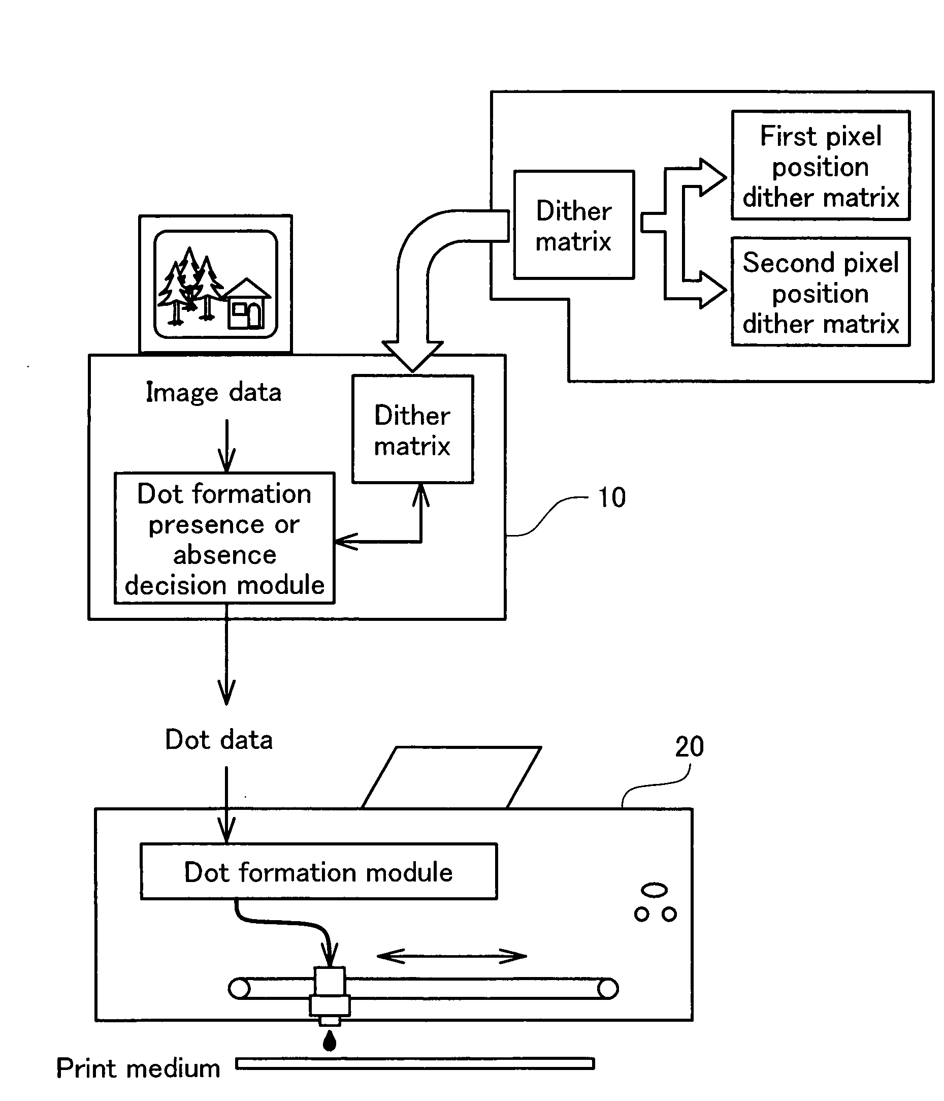
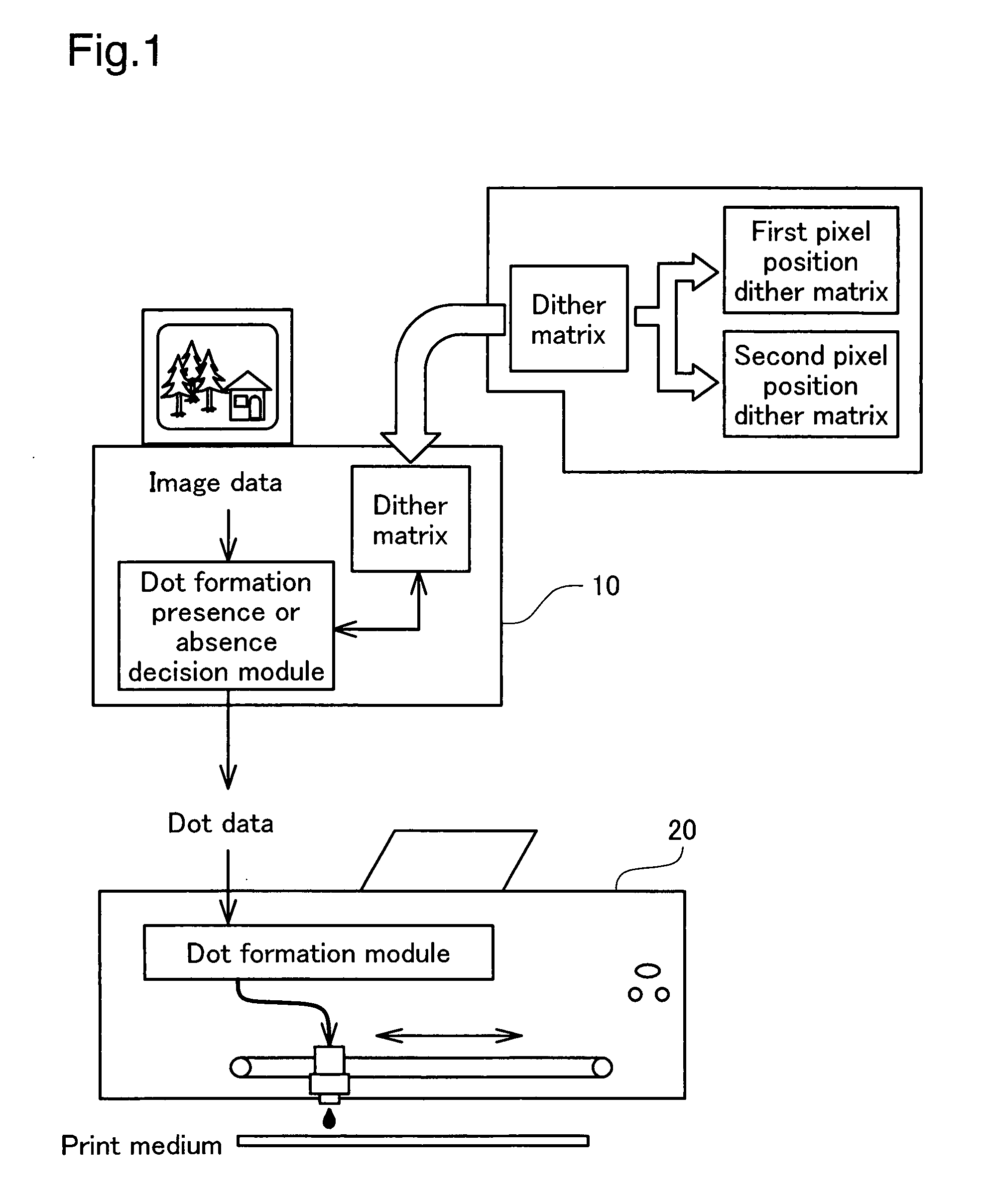
[0047]Before starting the detailed description of the embodiment, a summary of the embodiment is described while referring to FIG. 1. FIG. 1 is an explanatory drawing showing a summary of a printing system as the printing apparatus of this embodiment. As shown in the drawing, the printing system consists of a computer 10 as the image processing device, a printer 20 that prints the actual images under the control of the computer 10 and the like, and entire system is unified as one and functions as a printing apparatus.

[0048]A dot formation presence or absence decision module and a dither matrix are provided in the computer 10, ...


PUM


Abstract

The invention provides a printing method of performing printing on a print medium. The method includes: generating dot data representing a status of dot formation on each of print pixels of a print image to be formed on the print medium, by performing a halftone process on image data representing a input tone value of each of pixels constituting an original image; providing a print head and a platen; setting a platen gap as a distance between the print head and the platen to a single fixed value that is commonly applied to plural printing environments; and performing a main scan of the print head to form a dot in each of the print pixels on the print medium supported by the platen according to the dot data in each of a forward pass and a backward pass of the print head, for generating the print image. The performing includes combining dots formed on a first pixel position group with dots formed on a second pixel position group in a common print area to generate the print image, the first pixel position group including multiple print pixels as objects of dot formation in the forward pass of the print head, the second pixel position group including multiple print pixels as objects of dot formation in the backward pass of the print head. The generating dot data includes setting a condition of the halftone process to reduce potential deterioration of picture quality due to a positional misalignment between the dots formed on the first pixel position group and the dots formed on the second pixel position group.

Description

BACKGROUND[0001]1. Technical Field[0002]The present invention relates to a technique of forming dots on a print medium to generate a print image.[0003]2. Related Art[0004]Inkjet printers with bidirectional printing function have been used widely as the output device of computers. In the inkjet printers, on the assumption of a potential deflection (cockling) of a print medium due to ink absorption, a platen gap between a print head and a platen for holding the print medium is set to a sufficiently large value to prevent the cockled print medium from interfering with the print head. Setting a large value to the platen gap, however, causes a trade-off problem of an increased difference between the positions of ink dots formed in a forward pass and in a backward pass of the bidirectional printing.[0005]Multiple different types of print media including plain paper and photo paper are generally usable in the inkjet printers. The different types of print media have significantly different ...

Claims


Application Information

Patent Timeline
Patent Type & Authority Applications(United States)
IPC IPC(8): G06K15/00
CPCB41J2/15B41J19/145B41J25/308G06K15/107H04N1/4051
Inventor YAMAZAKI, SATOSHIKAKUTANI, TOSHIAKITAKAHASHI, TORUTANASE, KAZUYOSHI
Owner SEIKO EPSON CORP
Learn More