
Apparatus and methods for increasing the rate of solute concentration evolution in a supercritical process chamber

a supercritical process and solute concentration technology, applied in the direction of cleaning processes and apparatus, chemistry apparatus and processes, cleaning processes using liquids, etc., can solve the problems of presenting many engineering challenges, unable to be liquefied, and processes showing minimal selectivity for photoresist and post-etch residues

Inactive Publication Date: 2008-10-30
NOVELLUS SYSTEMS
View PDF20 Cites 197 Cited by
  • Summary
  • Abstract
  • Description
  • Claims
  • Application Information

AI Technical Summary

Benefits of technology

[0032]The method can involve purifying processing solution removed from the process vessel. The purified processing solution removed from the process vessel can be used in the step of preparing a supercritical processing solution. A further element of this invention may include conditioning of the supercritical solvent after it has exited the process vessel during its recirculation. This conditioning may include cooling of the super

Problems solved by technology

The fabrication of new-generation integrated circuits (IC) in the Ultra-large Scale Integration (ULSI) era poses many engineering challenges.
This means that if CO2 is heated above a temperature of 304.2° K, it cannot be liquefied no matter how high the pressure.
Such processes demonstrate minimal selectivity for photoresist and post-etch residue over the newer low-k dielectric materials currently in development.
Although supercritical fluids are finding acceptance in wafer cleaning regimens, they present many engineering challenges.
Most existing apparatus and methods lack flexibility and practicality.
Commonly, opening and closing such vessels is labor intensive.
Another disadvantage of traditional vessels is that opening and closing for wafer exchange involves moving heavy components.
Overcoming these high inertial loads makes wafer exchange in such systems inefficient.
Supercritical processes are hindered by another inefficiency, which relates to the time taken to pressurize and depressurize the process chamber.
Since a large amount of fluid is necessary to attain process pressures, pressurization and depressurization take a long time.
In a cost-sensitive environment, such as that of an IC manufacturer, this time is wasted since no actual process may take place during these periods.
Single-wafer processing, such as that commonly practiced in other steps of IC fabrication, is inherently inefficient in the context of supercritical processes because of the time lost to pressurization and depressurization.
This ultimately is bad for the environment and costly.
Another problem with regard to conventional supercritical cleaning processes is that they do not allow for easy adjustment in certain process conditions during the course of the process.
In these cases, conventional systems are inappropriate because they do not allow easy replacement of one cleaning solution with another in the process vessel, while maintaining supercritical conditions.
Otherwise a reduction in pressure, and consequently in that of the supercritical fluid density, could result in precipitation of the chemical agent and consequent contamination of the semiconductor wafer.
This method is inapplicable to those additives that do not mix well with the liquid solvent.
In other cases, the liquid solvent may be at a sufficiently low temperature that the chemical additive may freeze causing damage to mechanical devices such as pumps and filters.
Otherwise, introduction of a two-phase mixture into the process vessel may cause precipitation of the liquid additive onto the wafer surface.
However, this requires that a fresh feed of additive and solvent be provided at all times during the process.
This is inherently wasteful of both additive and solvent.

Method used


Image

  • Apparatus and methods for increasing the rate of solute concentration evolution in a supercritical process chamber
  • Apparatus and methods for increasing the rate of solute concentration evolution in a supercritical process chamber
  • Apparatus and methods for increasing the rate of solute concentration evolution in a supercritical process chamber

Examples


Embodiment Construction

[0077]In the following detailed description of the present invention, numerous specific embodiments are set forth in order to provide a thorough understanding of the invention. However, as will be apparent to those skilled in the art, the present invention may be practiced without these specific details or by using alternate elements or processes. For example, while the invention is described principally in terms of cleaning contaminants from a wafer, the invention can also be used for depositing films or otherwise treating wafers with supercritical solvent media. In some descriptions herein, well-known processes, procedures, and components have not been described in detail so as not to unnecessarily obscure aspects of the present invention.

[0078]In this application, the term “wafer” is used extensively. The term “wafer” generally refers to a semiconductor wafer as such wafer exists during any of many stages of integrated circuit fabrication thereon. Preferably the invention is used...


PUM

PropertyMeasurementUnit
Timeaaaaaaaaaa
Residence timeaaaaaaaaaa
Temperatureaaaaaaaaaa

Abstract

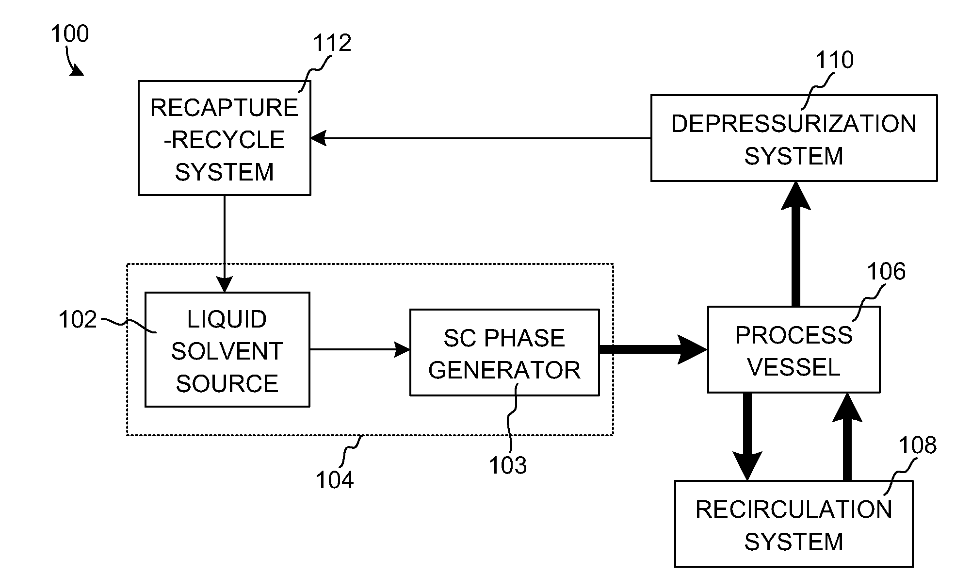
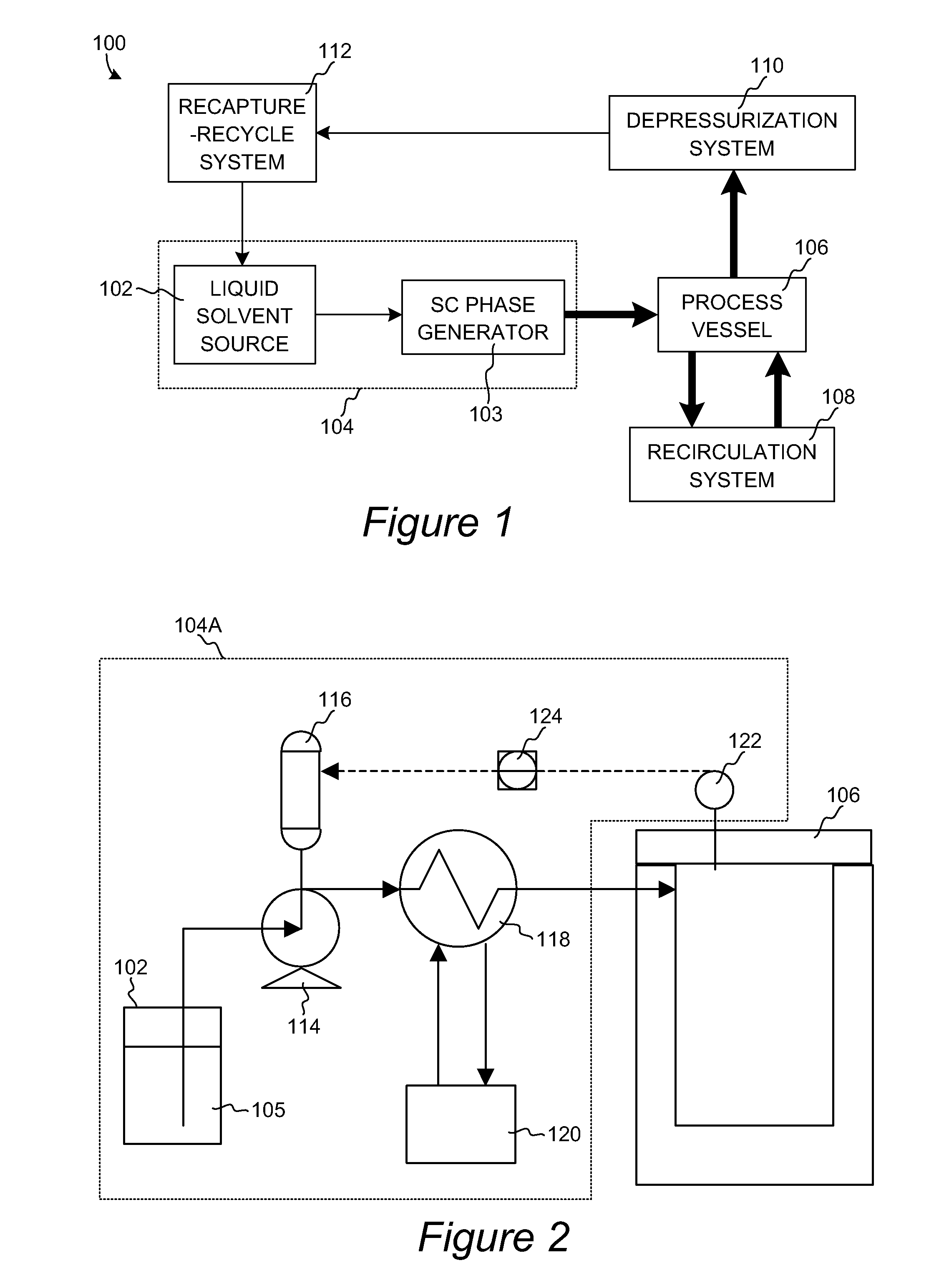
The present invention pertains to a system for processing semiconductor wafers. The processing may involve the removal of material from the wafers or deposition of material on the wafers. Various aspects of the invention include specialized pressurization, process vessel, recirculation, chemical addition, depressurization, and recapture-recycle subsystems. A solvent delivery mechanism can convert a liquid-state sub-critical solution to a supercritical processing solution and introduce it into a process vessel that contains a batch of wafers. The wafers may be rotated within the supercritical processing solution. The supercritical processing solution is preferably recirculated through the process vessel by a recirculation system. When chemical additives are added to a supercritical solvent, the momentum of the chemical additives are preferably matched to the momentum of the supercritical solvent. Additives may be added at a higher initial flow rate, then ramped down a lower flow rate, e.g., a steady-state flow rate.

Description

CROSS-REFERENCE TO RELATED APPLICATIONS[0001]This is a continuation-in-part of U.S. patent application Ser. No. 10 / 067,520, filed Feb. 5, 2002 and a continuation-in-part of U.S. patent application Ser. No. 10 / 458,048, attorney docket number NOVLP066, both of which are hereby incorporated by reference for all purposes.FIELD OF THE INVENTION[0002]This invention relates to methods and apparatus for processing semiconductor wafers using supercritical fluids. More particularly, it relates to using supercritical fluid systems for removing photoresist and post-etch residue from wafers, as well as for depositing materials on wafers using such systems.BACKGROUND OF THE INVENTION[0003]The fabrication of new-generation integrated circuits (IC) in the Ultra-large Scale Integration (ULSI) era poses many engineering challenges. The drive toward reducing individual device size, and to concurrently increase computing capability embedded in an IC, has led to the development and use of novel material...

Claims


Application Information

Patent Timeline
IPC IPC(8): C23G1/00B08B3/00
CPCB08B7/0021H01L21/67057
Inventor SHRINIVASAN, KRISHNANHOEK, WILBERT G.M. VAN DENJOYCE, PATRICKPRATT, THOMASTHOMAS, TIM
Owner NOVELLUS SYSTEMS
Learn More