Fluid heating device and exhaust gas purifying apparatus
a technology of flue gas purification and heating device, which is applied in the direction of lighting and heating apparatus, machines/engines, and heating arrangements. it can solve the problems of exhaust gas purification apparatus complex structure, low temperature of engine as heat source, and insufficient heat quantity of coolan
- Summary
- Abstract
- Description
- Claims
- Application Information
AI Technical Summary
Benefits of technology
Problems solved by technology
Method used
Image

Examples
first embodiment
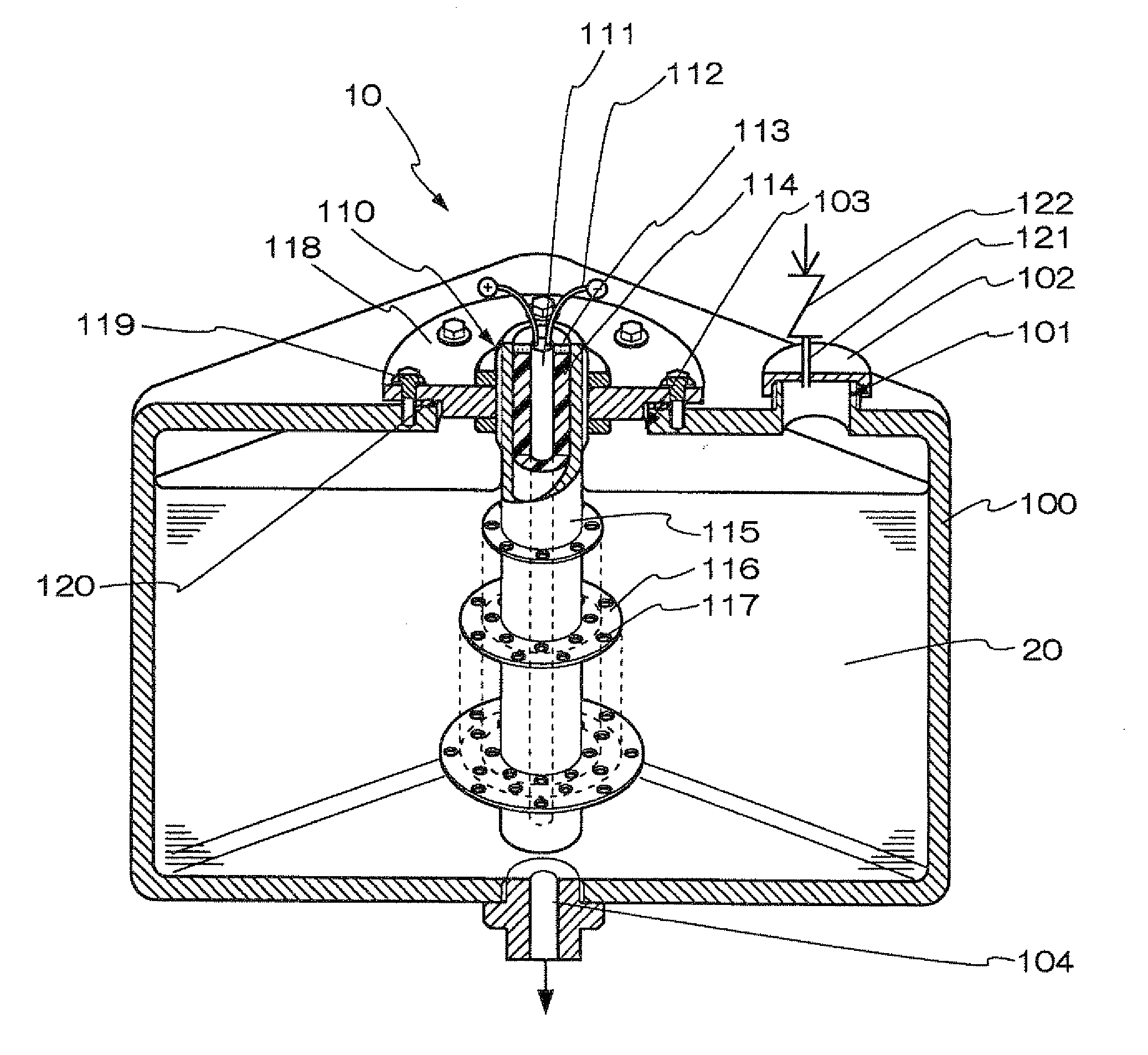
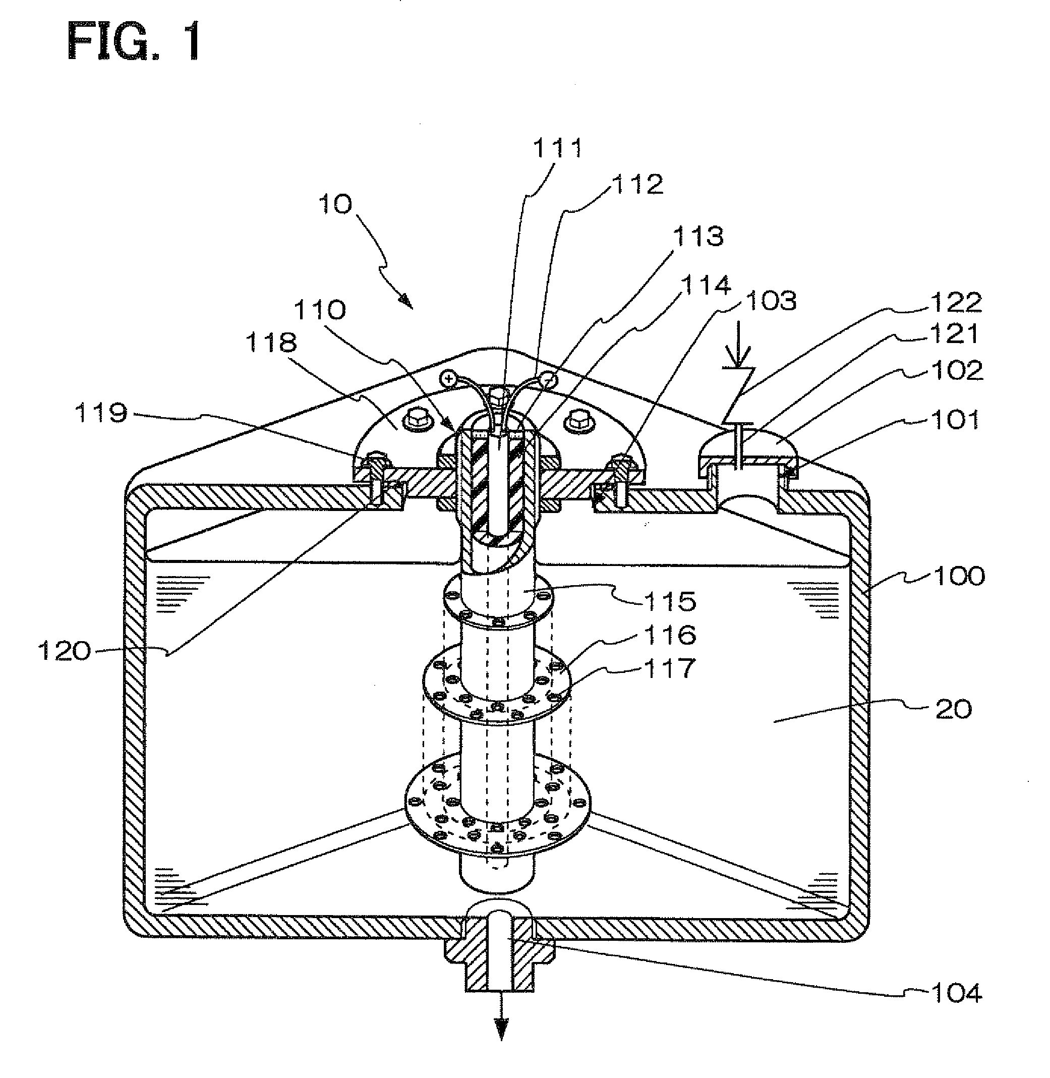
[0028]Referring to FIG. 1, a heating device 10 according to a first embodiment of the invention will be now described. The heating device 10 is suitably used for heating a urea aqueous solution 20, for example. The heating device 10 includes a tank 100 and a heat generator 110. The heat generator 110 includes a heating part 115 having a bottomed cylindrical shape, an insulating member 114 disposed in the heating part 115, a heat-generating element 111 having a rod shape and disposed in the heating part 115 through the insulating member 114, and a plurality of heat transfer sections 116. Each of the heat transfer sections 116 has a plate shape extending from an outer peripheral side of the heating part 115 to a radial outside of the heating part 115. A length of the heat generator 110 is set so that the heat generator 110 can heat the urea aqueous solution 20 between an upper portion and a lower portion of the tank 100. Each of the heat transfer sections 116 has a plurality of openin...
second embodiment
[0051]In the heat generator 110 in FIG. 1, the plural heat transfer sections 116, which extend from the heating part 115 to the radial outside of the heating part 115, are arranged to be parallel to each other along the axial direction of the heating part 115. Alternatively, the plural heat transfer sections 116 may be located to be connected without being limited to the shape shown in the example of FIG. 1.
[0052]In a heat generator 110a of a second embodiment of the invention shown in FIG. 5, a heat transfer section 116a has a single spiral plate shape located on the heating part 115 and extending along the axial direction of the heating part 115.
[0053]The heat transfer section 116a extends continuously in a spiral shape to have an upper part and a lower part in the axial direction of the heating part 115. The upper part of the heat transfer section 116a may have a dimension smaller than that of the lower part, in the radial direction of the heating part 115. The heat transfer sect...
third embodiment
[0056]In a heating device 10b in a third embodiment of the invention, a heat generator 110b are disposed at a bottom portion of a tank 100b, as shown in FIG. 7. That is, the heat generator 110b is inserted into the tank 100b via the bottom portion, and is fixed to the bottom portion. A cover 118b, bolts 119b, a sealing member 120b, and a first supply passage 104b in FIG. 7 are similarly with the cover 118, bolts 119, the sealing member 120, and the first supply passage 104 of the heating device 10 in FIG. 1, respectively. The heating device 10b has similar effects with those of the heating device 10.
PUM
 Abstract
Description
Claims
Application Information
 - R&D
- Intellectual Property
- Life Sciences
- Materials
- Tech Scout
- Unparalleled Data Quality
- Higher Quality Content
- 60% Fewer Hallucinations
Browse by: Latest US Patents, China's latest patents, Technical Efficacy Thesaurus, Application Domain, Technology Topic, Popular Technical Reports.
© 2025 PatSnap. All rights reserved.Legal|Privacy policy|Modern Slavery Act Transparency Statement|Sitemap|About US| Contact US: help@patsnap.com