
Interposer, a method for manufacturing the same and an electronic circuit package

a manufacturing method and electronic circuit technology, applied in the direction of fixed capacitor details, feed-through capacitors, printed circuit non-printed electric components association, etc., can solve the problems of potential degradation of the electrical characteristics of the capacitor, potential electric shortage between the capacitor electrode, and leakage of electric current, so as to prevent moisture absorption and reduce the effect of electrical degradation

Active Publication Date: 2008-10-09
IBIDEN CO LTD
View PDF9 Cites 53 Cited by
  • Summary
  • Abstract
  • Description
  • Claims
  • Application Information

AI Technical Summary

Benefits of technology

[0007]The present invention was designed to overcome the above-described problems. The objective of the present invention is to prevent moisture absorption at the dielectric in a capacitor and to produce a capacitor having little degradation of electrical characteristics.

Problems solved by technology

However, in a method in which a silicon capacitor is manufactured by forming a trench structure in a silicon substrate, it is expected that the dielectric in the capacitor will absorb moisture during the manufacturing process of the capacitor, and the leakage of electric current will expand.
Furthermore, when the capacitor is installed in a circuit package, potential electric shortages may occur between capacitor electrodes due to the absorbed moisture in the dielectric.
In a conventional capacitor, when a solution treatment is applied to exfoliate the support substrate from the interposer, potential degradation of the electrical characteristics of the capacitor may occur due to solution seepage into the dielectric or bond residue.

Method used


Image

  • Interposer, a method for manufacturing the same and an electronic circuit package
  • Interposer, a method for manufacturing the same and an electronic circuit package
  • Interposer, a method for manufacturing the same and an electronic circuit package

Examples


example 2

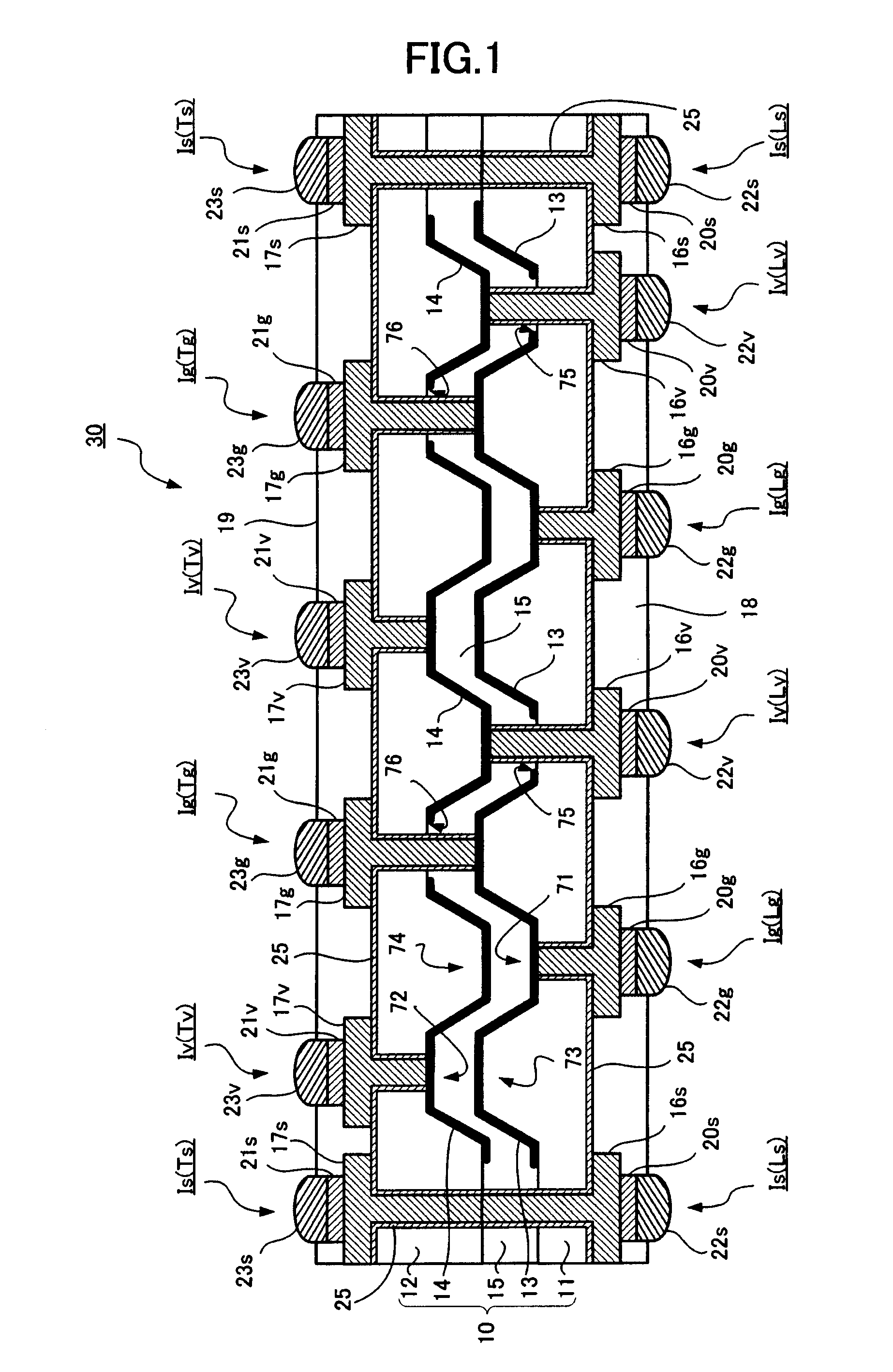
[0063]FIG. 6 is a cross-sectional view of an interposer having a differently structured capacitor related to an example of the present invention. According to Example 2, substrates 11, 12 are made of glass or ceramic.

[0064]According to the example shown in FIG. 6, substrates 11, 12 are made of glass, and concaves 71, 72 are formed by etching using, for example, hydrofluoric acid (HF) or the like. The example in FIG. 6 shows that concaves having an almost rectangular cross-sectional shape are formed by isotropic etching. In this example, concaves 71, 72 and convexes 73, 74 are also formed in such a way that the concave-convex structures on substrates 11, 12 align with each other. Convex 73 of substrate 11 aligns with concaves 72 of substrate 12 while maintaining a space in between; and convex 74 of substrate 12 aligns with concave 71 of substrate 11 while maintaining a space in between. Electrodes 13, 14 are formed along the concave-convex structures formed on each facing surface of ...


PUM

PropertyMeasurementUnit
Thicknessaaaaaaaaaa
Dielectric polarization enthalpyaaaaaaaaaa
Electrical conductoraaaaaaaaaa

Abstract

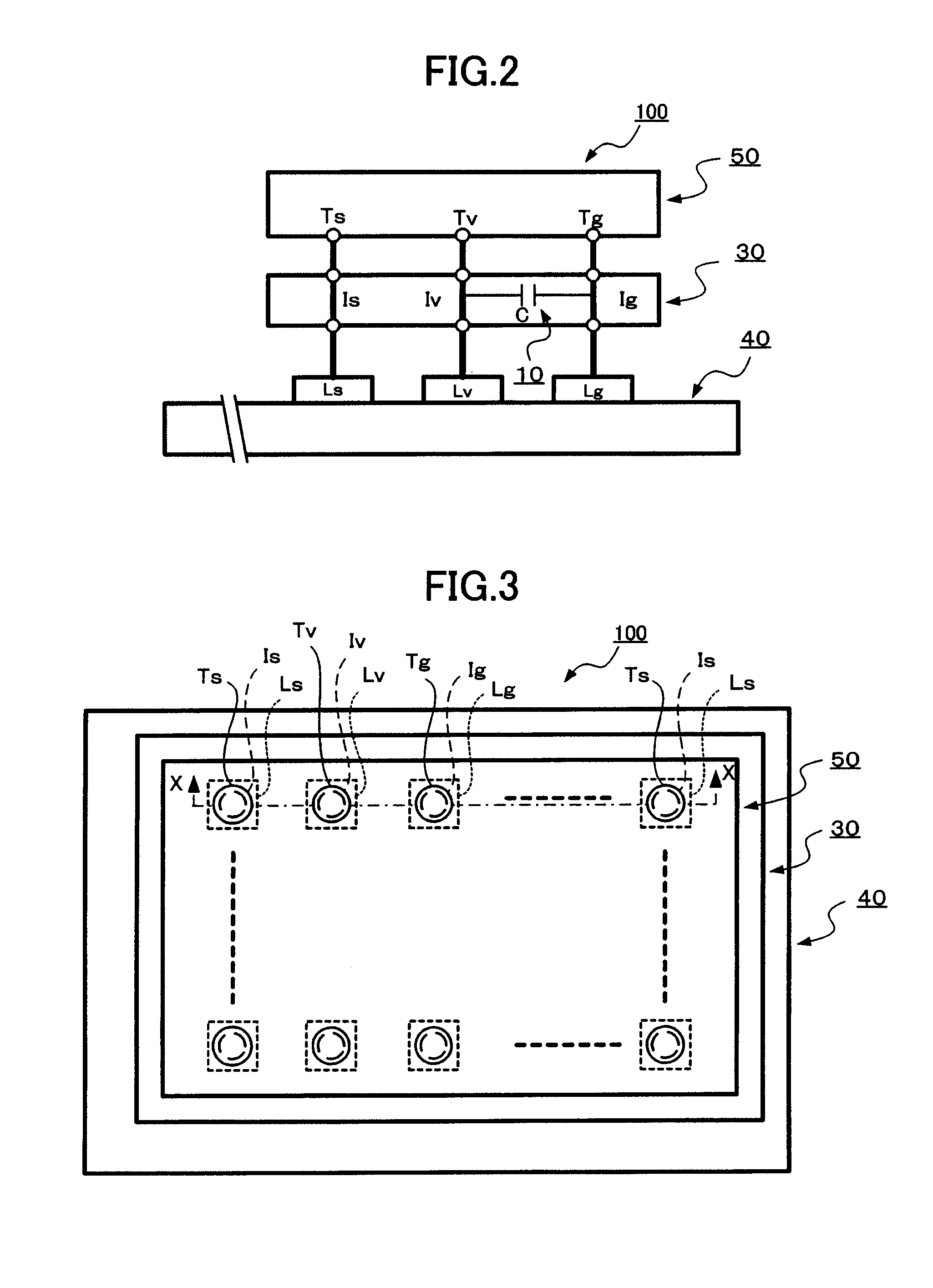
An interposer including: a substrate including a first layer and second layer, wherein the first layer and second layer are positioned parallel to each other; electrodes each having a concave-convex structure formed on each facing surface of the first layer and second layer of the substrate; a dielectric layer sandwiched between the electrodes which are formed on each facing surface of the first layer and second layer of the substrate; a first conductive part which vertically passes through the first layer of the substrate from a first outer surface of the substrate and is electrically connected to an electrode formed on a surface of the second layer of the substrate that faces the first layer of the substrate; and a second conductive part which vertically passes through the second layer of the substrate from a second outer surface of the substrate and is electrically connected to an electrode formed on a surface of the first layer of the substrate that faces the second layer of the substrate.

Description

FIELD OF THE TECHNOLOGY[0001]The present invention is related to an interposer having a capacitor to mount electronic components such as an IC, a method for manufacturing the interposer and an electronic circuit package.BACKGROUND TECHNOLOGY[0002]To prevent noise or the like which occurs in electronic circuits, and to maintain a steady function of semiconductor IC equipment and the like, a capacitor such as a bypass capacitor or a decoupling capacitor is connected between signal terminals and ground circuits, or between power-source terminals and ground circuits of a semiconductor IC component. Also, an interposer made of a silicon substrate is used, for example, between a semiconductor chip and a wiring substrate, or used as a relay substrate to form interlayer interconnections in a semiconductor chip. Technology to form the above-mentioned capacitor in an interposer has been already developed.[0003]For example, a method to form a capacitor on a silicon substrate is described in Pu...

Claims


Application Information

Patent Timeline
IPC IPC(8): H01G4/35H01R43/20
CPCH01G4/01Y10T29/49165H01G4/35H01G4/236H01L2224/16265H01L2924/15311H01L2924/157H01L2924/19011H01L2924/19041H01L2924/19103
Inventor KAWANO, SHUICHICHEN, LIYI
Owner IBIDEN CO LTD
Learn More