
Resin coated seamless can

a seamless can and resin coating technology, applied in the field of resin coating seamless cans, can solve the problems of general corrosion under film corrosion, difficult resin coating of metal sheets, and easy progress of resin coating under film corrosion, etc., to prevent taste change, maintain corrosion resistance, and shock resistance

Active Publication Date: 2008-10-02
TOYO SEIKAN KAISHA LTD
View PDF4 Cites 10 Cited by
  • Summary
  • Abstract
  • Description
  • Claims
  • Application Information

AI Technical Summary

Benefits of technology

[0048]That is, it is possible to obtain advantageous effects that adhesiveness on an adhesive interface formed between the coated resin layer and the surface of the metal substrate is enhanced, corrosion under film (UFC) of the seamless can is suppressed, and shock resistance (dent resistance) of the film is enhanced.
[0049]Further, it is also possible to obtain an advantageous effect that even when the seamless can is stored in a form of a canned product, an absorption of a flavor of a content by resin is prevented or when the canned product is opened to be served for drinking or eating, the change of taste is prevented.
[0050]Still further, in the resin-coated seamless can according to the present invention, it is preferable that the density of the polyester resin layer at the inner surface side of the can bottom portion or the inner surface side of the can bottomed portion and the inner surface side of the can-barrel lower portion is set to equal to or less than 1.36.
[0051]In the resin-coated seamless can according to the present invention, the orientation state of the resin-coated layer at the can bottom portion shows the orientation state of the resin-coated layer before working. Accordingly, to enable the resin-coated layer at the can bottom portion to follow the severe working of the can barrel portion, it is necessary to maintain the orientation state of the coated resin layer at the can bottom portion substantially in the non-oriented state. Further, it is possible to maintain corrosion resistance, shock resistance and the like in the satisfying state by sufficiently ensuring adhesiveness on the adhesive interface formed between the resin-coated layer and the surface of the metal substrate at the can bottom portion.
[0052]The endowment of the above-mentioned characteristics on density of the resin-coated seamless can be conducted in view of the orientation state of the coated polyester resin before working, the forming condition of the seamless can, the heat treatment after forming the seamless can and the like.
[0053]To control the density of the resin-coated seamless can, it is necessary to perform following steps. That is, the substantially non-oriented polyester resin-coated metal sheet which is produced by extruding and coating molten resin on a surface of a metal sheet or laminating a cast film on the surface of the metal sheet is used. The resin-coated metal sheet is formed into a seamless cap by thinning drawing forming and / or ironing working under an appropriate temperature condition. Thereafter, the seamless cap is subjected to the heat treatment so that a strain (a residual stress) of the coated resin layer of the can barrel portion which is caused by working is alleviated and the molecules are orientated and crystallized.

Problems solved by technology

Accordingly, it has been difficult for a resin-coated metal sheet for can use which has been conventionally adopted and is formed by laminating a biaxially stretched film on a metal sheet by heat adhesion to catch up with the harsh demand for working which becomes stricter year by year.
With respect to corrosion resistance of the seamless can formed of the thermoplastic resin-coated metal sheet, corrosion under a film which is referred to as an under film corrosion (UFC) in general is liable to progress.

Method used


Image

  • Resin coated seamless can
  • Resin coated seamless can
  • Resin coated seamless can

Examples


example 1

[0120]Polyester resin having the composition C shown in Table 1 was charged into a biaxial extruder, was extruded through T dies to form films having a thickness of 20 μm. The films were cooled by cooling rollers and the cooled film were wound to form cast films. Thereafter, the films formed in the above manner were thermally laminated to both surfaces of an aluminum alloy sheet (sheet thickness: 0.28 mm, A3004 material, chromic acid / phosphate surface treatment). The lamination was immediately followed by water cooling thus obtaining a polyester resin-coated metal sheet. The temperature of the metal sheet before the lamination was set to a temperature 15 degree centigrade higher than a melting point of polyester resin and the lamination was performed by setting a temperature of lamination rolls to 150 degree centigrade and at a sheet travelling speed of 40 m / min thus producing the resin-coated metal sheet.

[0121]The polyester resin-coated metal sheet produced in this manner was coate...

example 2

[0127]A seamless can was produced by a method similar to the method of the example 1 except for that this embodiment used polyester resin having the composition D shown in FIG. 1.

example 3

[0128]A seamless can was produced by a method similar to the method of the example 1 except for following conditions. That is, in this embodiment, polyester resin having the composition B shown in Table 1 which constitutes a surface layer and the polyester resin having the composition D shown in Table 1 which constitutes a lower layer were charged into two biaxial extruder and were extruded through a two-layer T-die thus forming a two-layered cast film, wherein a thickness of the surface layer was 5 μm and a thickness of the lower layer was 15 μm. Thereafter, a laminated material was obtained by using the cast film.


PUM

PropertyMeasurementUnit
densityaaaaaaaaaa
densityaaaaaaaaaa
thicknessaaaaaaaaaa
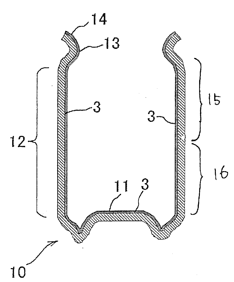
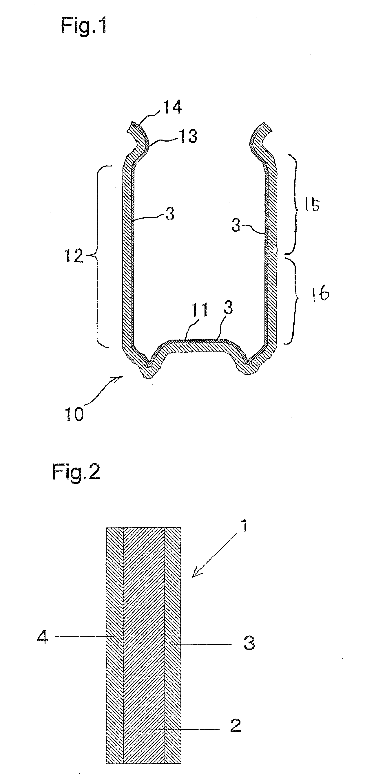

Abstract

A resin-coated seamless can of the present invention is a resin-coated seamless can formed of a resin-coated metal sheet 1 which is produced by coating a polyester resin layer 3 containing polyethylene terephthalate onto a surface of a metal substrate 2, wherein the density of a polyester resin layer of a can inner surface side is set to equal to or more than 1.36 at a can barrel upper portion. Further, an infrared dichroic ratio (R1) of the polyester resin layer at the inner surface side of the can barrel portion which is expressed by a following formula (1) is set to equal to or more than 1.1. R1=Iw(⊥) / Iw(∥) . . . (1). In the formula (1), Iw(⊥) indicates an infrared absorption intensity of 973 cm−1 with respect to polarized infrared rays perpendicular to the can height direction at the can barrel portion, and Iw(∥) indicates an infrared absorption intensity of 973 cm−1 with respect to polarized infrared rays parallel to the can height direction at the can barrel portion.

Description

BACKGROUND OF THE INVENTION[0001]1. Field of the Invention[0002]The present invention relates to a resin-coated seamless can, and more particularly to a resin-coated seamless can which exhibits excellent corrosion resistance and excellent shock resistance.[0003]2. Description of the Related Art[0004]Conventionally, as a side seamless can, there has been known a can which is produced by a following method. That is, a metal blank such as an aluminum plate, a tin plate or a tin-free steel plate is subjected to at least one drawing stage. The drawing stage is conducted between a drawing die and a punch to form a cylindrical cup comprising a barrel portion free of seams on a side surface thereof and a bottom portion integrally connected to the barrel portion which is also free of seams. Then, if desired, the barrel portion may be subjected to ironing between an ironing punch and a die to reduce the thickness of the barrel portion (drawing / ironing working).[0005]Further, in place of such ...

Claims


Application Information

Patent Timeline
Patent Type & Authority Applications(United States)
IPC IPC(8): B32B15/08B65D8/16B32B15/09B65D1/12B65D1/16B65D25/14B65D25/34B65D65/42
CPCB32B15/08B65D1/165B65D65/42Y10T428/1352Y10T428/1355Y10T428/13Y10T428/139Y10T428/1359Y10T428/1303B65D1/12B32B15/09B32B2367/00B32B27/36
Inventor SATOOHASHI, KAZUAKI
Owner TOYO SEIKAN KAISHA LTD
Learn More