
Imaging of materials

Active Publication Date: 2008-10-02
KROMEK
View PDF3 Cites 27 Cited by
  • Summary
  • Abstract
  • Description
  • Claims
  • Application Information

AI Technical Summary

Benefits of technology

[0017]It is an object of the present invention to mitigate some or all of the above disadvantages of prior art line scanning systems.
[0018]It is a particular object of the present invention to provide a method and apparatus for line scanning of objects, and especially of containers of multiple objects or objects comprising multiple components, which provides additional information about their shape and / or location in three-dimensional space.
[0019]It is a particular object of the invention to provide a method and apparatus which generates an image providing information about the shape and / or location of objects in three dimensional space which does not require special viewing apparatus but can be presented effectively on a two dimensional viewing screen.

Problems solved by technology

Even so, the image generated by such an X-ray apparatus is limited.
This can make it difficult to interpret.
However it does not give information as to the nature of the items which have been located.
Although stereoscopic imaging can be a relatively powerful technique, exploiting full physiological cues in relation to depth information, and thus offering the potential for a user of the X-ray apparatus to identify objects or components much more readily and clearly, it can be complex in practical operation.
For these reasons, full stereoscopic imaging has not gained wide acceptance for scanning machines of this type.
Not only do conventional non-stereoscopic apparatus and methods tend to give limited information in a third dimension, but also the images they produce also give limited information about the material content.
However, even such a system confers only limited information about composition.
Even so, the compositional information given by the arrangement is still limited, for example in that the low / higher energy duality effect can give only a crude approximation of an organic / inorganic split and cannot itself distinguish polycrystalline materials.
This technique of identifying materials from the scattered signal though possible is not currently commercially used as the extra scatter detectors introduce greater complexity in the system and the scattered beams are weak and so throughput is limited.

Method used


Image

  • Imaging of materials
  • Imaging of materials
  • Imaging of materials

Examples


Embodiment Construction

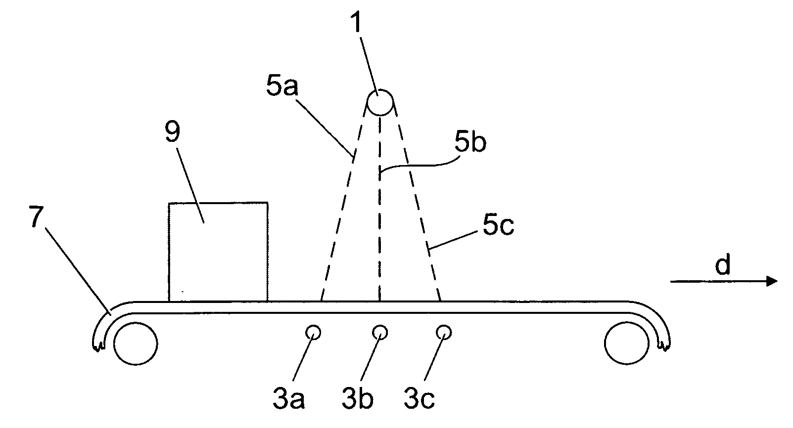
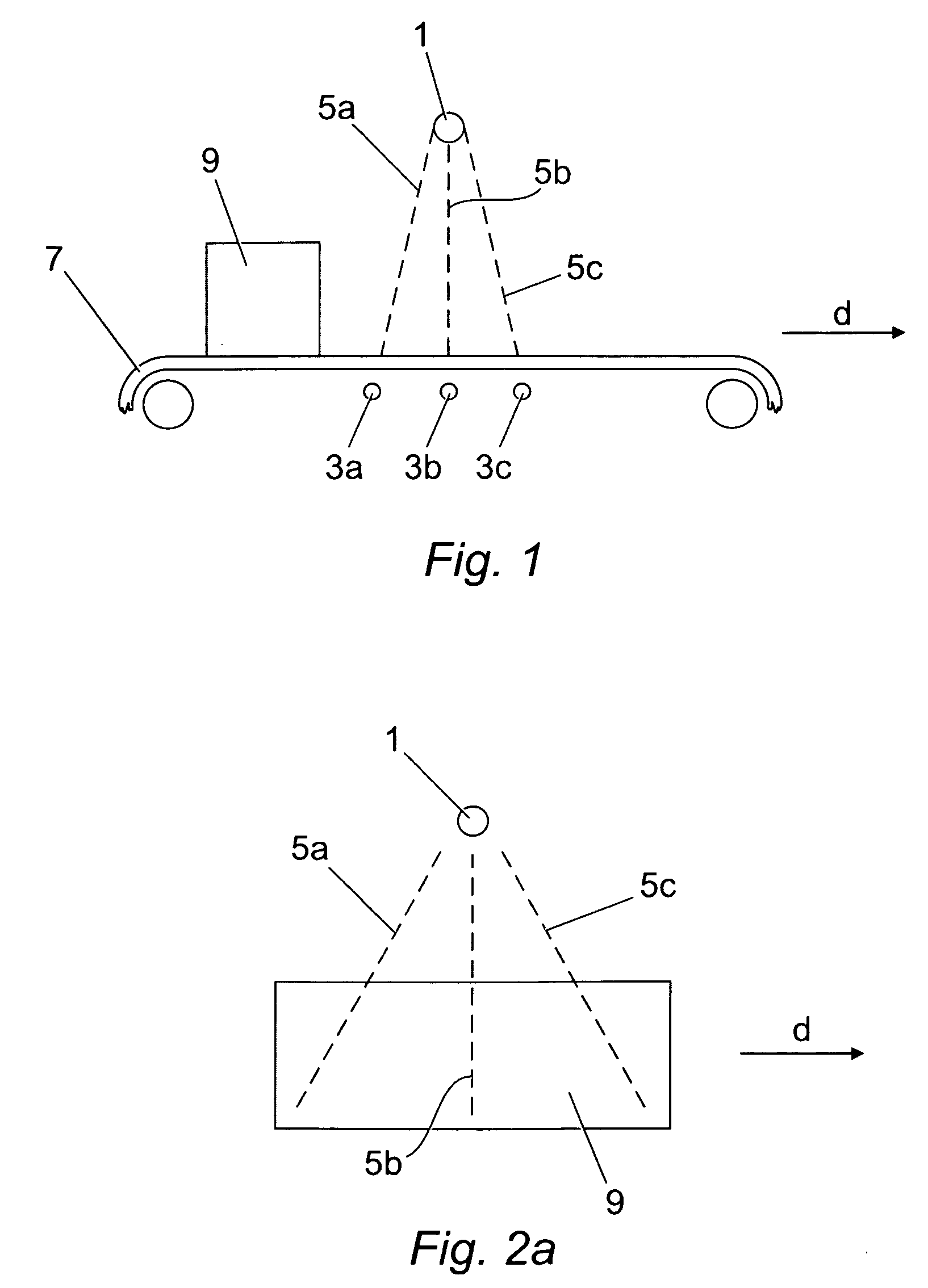
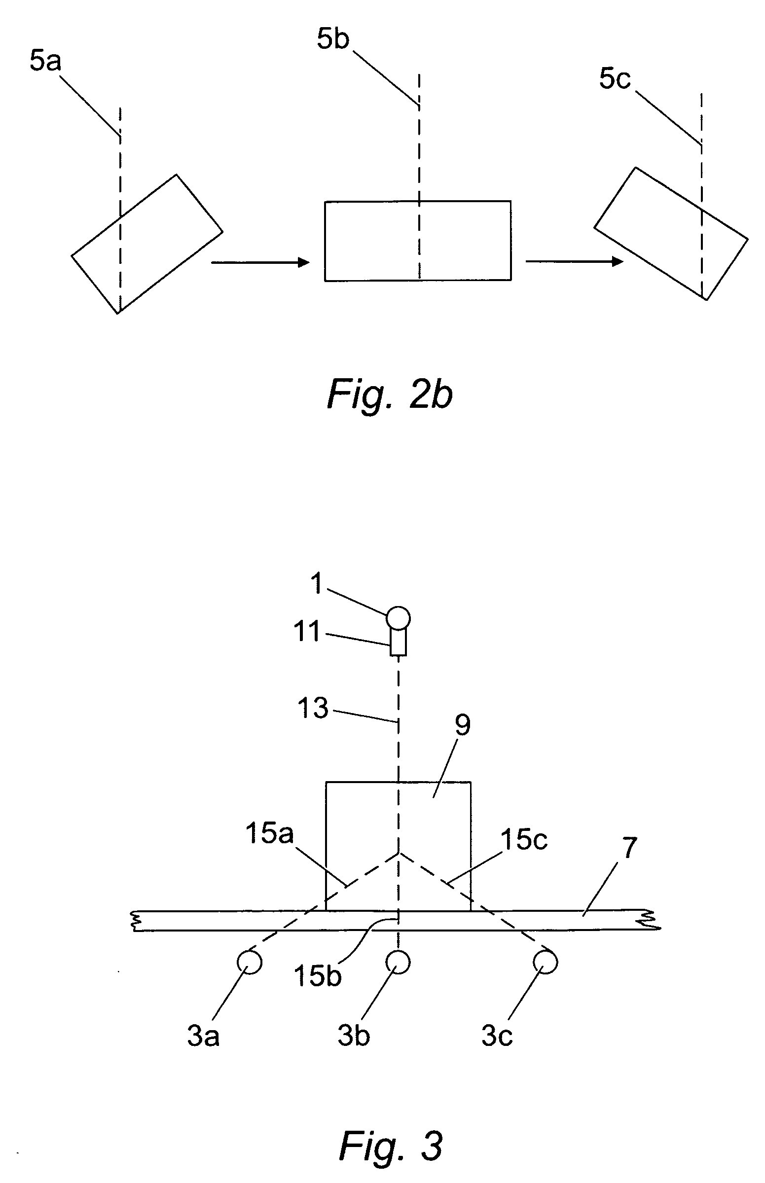
[0086]Referring to FIG. 1, a suitable X-ray source 1 is used to direct X-rays via a scanning zone in the direction of three linear array detectors 3a to 3c.

[0087]In the embodiment, the linear array detectors 3a to 3c comprise material capable of spectroscopic resolution of incident X-rays, and in the specific example comprise cadmium telluride although the skilled person will appreciate that other material selections may be appropriate. To exploit this spectral resolution, the X-ray source emits X-ray across a broad energy spectrum. In the example a tungsten source is used, although the skilled person would appreciate that other materials might be appropriate.

[0088]Incident ray paths 5a to 5c are shown through the scanning zone between the X-ray source 1 and, respectively, the detectors 3a to 3c.

[0089]An endless belt conveyor 7 causes an object to be scanned 9 to move in a direction d so as to intercept the ray paths 5a to 5c in the scanning zone. The envisaged application of this...


PUM


Abstract

An apparatus and method for obtaining an image of an object. The apparatus comprises a radiation source and a series of two to five linear detectors spaced therefrom to define a scanning zone; means to cause an object to move relative to and through the scanning zone; a direct image generation apparatus to generate an image from the output of a linear detector; an intermediate image generation apparatus configured to generate at least one intermediate image from an adjacent pair of linear detectors, by processing the output of the pair of detectors and generating an image representative of an output intermediate between the two said detector outputs; the image apparatus adapted such that at least five and preferably at least six images are generated in total; an image display adapted successively to display such images and thus display the monocular movement parallax between the images.

Description

FIELD OF THE INVENTION[0001]This invention relates to a method and apparatus for detecting, imaging and in a preferred embodiment, characterising material in three-dimensional space.[0002]The invention in particular relates to an apparatus and method making use of high energy radiation such as X-rays or gamma-rays to scan objects where it is desirable to gain information about their internal contents and / or composition. The invention in particular relates to an apparatus and method operating on the line-scan principle, in which three dimensional objects are caused to move through a scanning zone and imaging information collected. These principles are widely employed for example in the security industry, to scan objects where it is desirable to gain information about their internal contents, but might also be employed in other areas, for example, without limitation, medical imaging, imaging for quality control purposes or the purposes of determining the integrity of the structure, o...

Claims


Application Information

Patent Timeline
IPC IPC(8): G01T1/24
CPCG01V5/0058G01V5/228
Inventor ROBINSON, MAX
Owner KROMEK
Learn More