NMR spectrometer

a spectrometer and nuclear magnetic resonance technology, applied in the field of nuclear magnetic resonance spectrometers, can solve the problems of affecting the sensitivity of nmr spectrometers, affecting the sensitivity of spectrometers, and affecting the application of high-sensitivity nmr spectrometers, so as to improve the q factor, reduce the resistance of the entire antenna, and improve the effect of the effect of the effect of the effect of the resistance loss

Inactive Publication Date: 2008-09-25
HITACHI LTD
View PDF7 Cites 15 Cited by
  • Summary
  • Abstract
  • Description
  • Claims
  • Application Information

AI Technical Summary

Benefits of technology

[0008]An object of the present invention is therefore to provide a high-sensitivity NMR spectrometer having a superconducting probe antenna that achieves a high Q factor and prevents deterioration in magnetic homogeneity of a static magnetic field in a sample space.
[0011]In the present invention, the probe antenna is formed by using a wire having a superconducting layer of a thickness from several hundred nm to several μm formed on the surface of a metal wire. The probe antenna is fixed by being wound around a cylindrical bobbin made of a dielectric. The probe antenna is an LC resonant circuit, and a radio-frequency current flows to the conductor of the antenna upon detection of a signal from the sample. At this time, the flowing radio-frequency current converges to the surface of the conductor of the antenna due to the conductor skin effect. For this reason, it is possible to reduce a resistive loss in the entire antenna, and to thus improve a Q factor, by forming a superconducting thin film of a low resistance on the surface of the conductor of the antenna.
[0012]According to the present invention, it is possible to reduce a resistive loss in the entire antenna, and to thus improve a Q factor. This is achieved by forming a superconducting thin film of a low resistance disposed on the surface of a conductor for the antenna which a radio-frequency current converges to and passes through upon detection of a signal.
[0013]In addition, the volume of the superconducting layer formed on the surface of the metal wire is very small. Accordingly, it is possible to significantly suppress disturbance of the static magnetic field due to the diamagnetic property of the superconductor, as compared with a conventional antenna formed by using a superconducting wire or a superconducting bulk. Moreover, in the present invention, the antenna is formed by winding, around a dielectric cylindrical bobbin, a composite metal wire fabricated by forming the superconductor on the metal wire. This configuration eliminates the need for a dielectric substrate used for formation of a superconducting thin film, as in the case of a conventional probe antenna using a superconducting thin film. As a result, it is possible to greatly reduce the volume of a dielectric to be used, as compared with the conventional superconducting thin film probe antenna.
[0014]In addition, the present invention makes it possible to achieve a smaller magnetic susceptibility of the metal wire forming the superconductor than that of a dielectric substrate. Concurrently, the present invention also makes it possible to achieve a smaller volume necessary for the configuration of the antenna than that of the dielectric substrate used in the conventional superconducting thin film probe antenna. As a result, according to the configuration of the present invention, it is possible to suppress a magnetic moment induced by members other than the super conductor required for the antenna configuration, as compared with the configuration of the conventional superconducting thin film probe antenna. Moreover, in the conventional superconducting thin film probe antenna, plural dielectric substrates are discretely disposed in a uniform magnetic field space. By contrast, in the present invention, the antenna can be formed by using a single cylindrical bobbin of excellent symmetry. With this antenna configuration, a distribution pattern of an error magnetic field by the dielectric is simplified, and it becomes easy to ensure the magnetic homogeneity by shimming.
[0015]As described above, the reduction in volume and the improvement in shape of the dielectric make it possible to suppress disturbance of the static magnetic field to a level enabling a highly-sensitive NMR measurement. Here, the disturbance occurs due to members other than the superconductor, which constitute the antenna. Accordingly, the present invention makes it possible to achieve a probe antenna having a very high Q factor resulting from the distinctive low loss property of a superconductor. Concurrently, the present invention makes it possible to achieve the probe antenna capable of maintaining the magnetic homogeneity of a static magnetic field in a sample space. As a result, it is possible to achieve an improvement in signal detection sensitivity in an NMR measurement.

Problems solved by technology

However, the probe antenna using the superconductor has the large problem that the magnetic homogeneity of a static magnetic field in a test sample space is disturbed due to the diamagnetic effect, which is characteristic of the superconductor.
This results in a decrease in the sensitivity of the spectrometry (that is, the S / N ratio).
Therefore, the probe antenna made of a bulk superconductor, a conventional superconducting multi-core wire material, or the like has difficulty in being applied to a high-sensitivity NMR spectrometer, due to the superconductor of great volume and hence a significant impairment in the magnetic homogeneity of the static magnetic field.
However, the probe antenna has the problem that the magnetic homogeneity of the static magnetic field deteriorates due to a magnetic moment produced by a dielectric substrate.
This problem occurs because the dielectric substrate, such as sapphire having the superconducting thin film formed thereon, is of great volume.
With this arrangement, it is very difficult to use shimming to ensure the magnetic homogeneity, because a distribution pattern of an error magnetic field in the sample space becomes complicated.

Method used


Image

  • NMR spectrometer
  • NMR spectrometer
  • NMR spectrometer

Examples


first embodiment

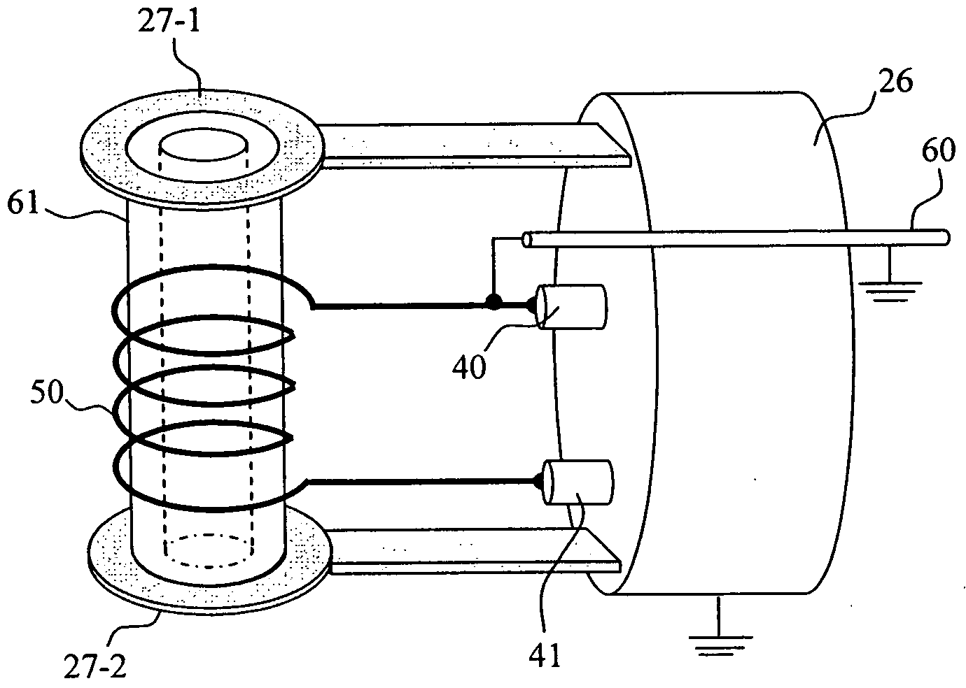
[0030]FIG. 1A is a perspective view showing the general configuration and arrangement of a principal constituent part of an NMR spectrometer to which the present invention is applied. Two separate superconducting magnets 10-1 and 10-2 produce a uniform magnetic field (that is, a uniform static magnetic field) 11 along the central axis. This uniform magnetic field 11 is indicated by the arrow B0 in FIG. 1A. A sample tube 30 with a sample 31 housed therein is inserted from a direction perpendicular to the uniform magnetic field (e.g., the direction of the x-axis in FIG. 1A). A cryogenic probe 20 incorporating a solenoidal-shaped probe antenna 25 that detects a signal from the sample 31 is inserted in the same direction as that of the uniform magnetic field. The cryogenic probe 20 is constituted of the probe antenna 25, a heat exchanger 22, a cold gas line 37, a probe tip stage 26, and a probe housing 23. The heat exchanger 22 is provided at the end portion of a cryocooler 29 that acts...

second embodiment

[0041]The second embodiment proposes an NMR spectrometer including a solenoidal-shaped probe antenna, as in the case of the first embodiment. The second embodiment uses a different antenna circuit configuration from that of the first embodiment. The basic configuration of the spectrometer, and the structure of the wire for the antenna coil are the same as those of the first embodiment shown in FIGS. 1A and 1B and FIG. 2.

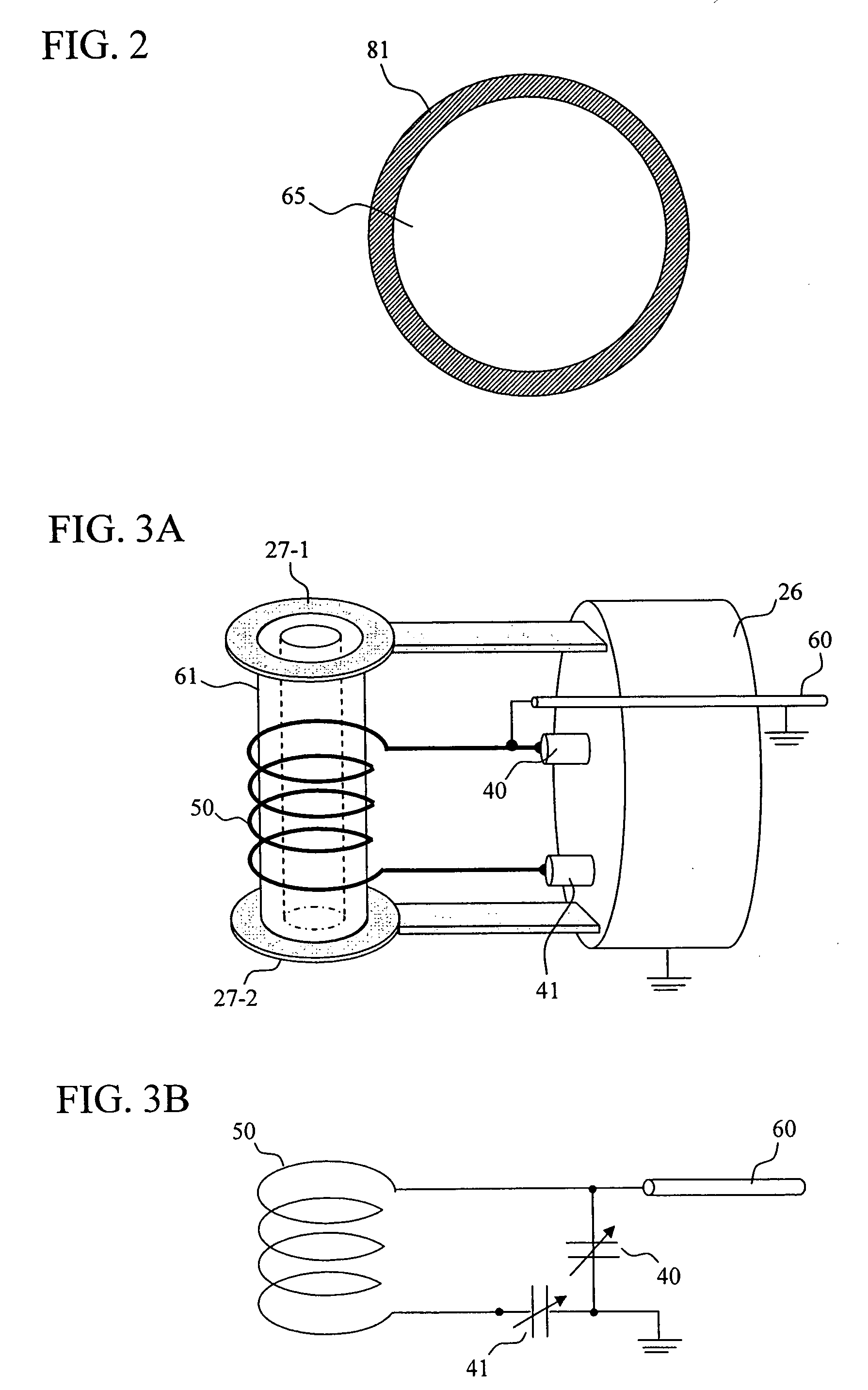
[0042]FIG. 4A is a perspective view schematically showing the solenoidal-shaped antenna coil according to the second embodiment mounted on the cryogenic probe 20. FIG. 4B is a view schematically showing an electrical connection of the probe antenna. A Cu wire for 1 mm diameter is wound four turns to be formed into a solenoidal-shaped antenna coil 50. Then, a tap lead 45 made of a Cu wire for 1 mm diameter is connected to a substantially middle point of the antenna coil 50 by a pulse heat bonding method. Thereafter, a superconducting magnesium diboride (MgB2) thin fil...

third embodiment

[0050]The third embodiment proposes an NMR spectrometer including a solenoidal-shaped probe antenna constituted of a plurality of antenna coils connected to each other. The basic configuration of this spectrometer is the same as those of the first and second embodiments. A wire used for each probe antenna has a structure in which a superconducting layer is formed on the surface of a metal wire as shown in FIG. 2, as in the cases of the first and second embodiments.

[0051]FIG. 5 schematically shows electrical connection of the solenoidal-shaped probe antenna according to the third embodiment. A Cu wire for 1 mm diameter, which is a base material for the wire for each antenna coil, is wound two turns to be formed into the solenoidal-shaped antenna coil. Then, a superconducting magnesium diboride (MgB2) thin film of 1 μm thickness is formed on the surface of the antenna coil by evaporation method. Two two-turn antenna coils 50-1 and 50-2 thus fabricated are disposed to positions where t...


PUM


Abstract

The present invention provides a highly-sensitive nuclear magnetic resonance (NMR) spectrometer which achieves a high Q factor using a superconductor, and concurrently which is provided with a probe antenna maintaining the magnetic homogeneity of the static magnetic field in a sample space. An antenna coil is fabricated by using a wire having a superconducting layer formed on the surface of a metal wire.

Description

CLAIM OF PRIORITY[0001]The present application claims priority from Japanese application JP 2007-076822 filed on Mar. 23, 2007, the content of which is hereby incorporated by reference into this application.BACKGROUND OF THE INVENTION[0002]1. Field of the Invention[0003]The present invention relates to a nuclear magnetic resonance spectrometer (hereinafter referred to simply as an “NMR spectrometer”), and more particularly to an NMR spectrometer characterized by a probe antenna that is used for applying a radio-frequency signal at a predetermined resonance frequency to a sample placed in a uniform magnetic field, and / or for receiving a free induction decay signal (or an FID signal).[0004]2. Description of the Related Art[0005]Nuclear magnetic resonance (NMR) spectrometry is a measurement approach that is capable of obtaining information on a substance at the atomic level, and hence that is excellent for observation of the structure of a compound. The fundamental principle of the mea...

Claims


Application Information

Patent Timeline
IPC IPC(8): G01R33/31
CPCG01R33/30G01R33/307G01R33/34007G01R33/34023G01R33/56536G01R33/34053G01R33/34069G01R33/34076G01R33/34046
Inventor YAMAMOTO, HIROYUKISAITOH, KAZUOHASEGAWA, HARUHIROTAKAHASHI, MASAYAOKADA, MICHIYA
Owner HITACHI LTD
Why Eureka
Try Eureka