
Method and apparatus for cooling integrated circuit chips using recycled power

a technology of integrated circuit chips and power, applied in the direction of lighting and heating apparatus, machine operation mode, etc., can solve the problems of increasing the density and complexity of integrated circuits (ics), increasing power consumption and heat dissipation of ics, and quickly reaching unsafe operating temperatures for power-demanding system components such as cpus or graphics processing units (gpus). , to achieve the effect of recycling wasted energy within the computer system and reducing the operating temperature of the ic chip

Inactive Publication Date: 2008-09-25
SUN MICROSYSTEMS INC
View PDF18 Cites 40 Cited by
  • Summary
  • Abstract
  • Description
  • Claims
  • Application Information

AI Technical Summary

Benefits of technology

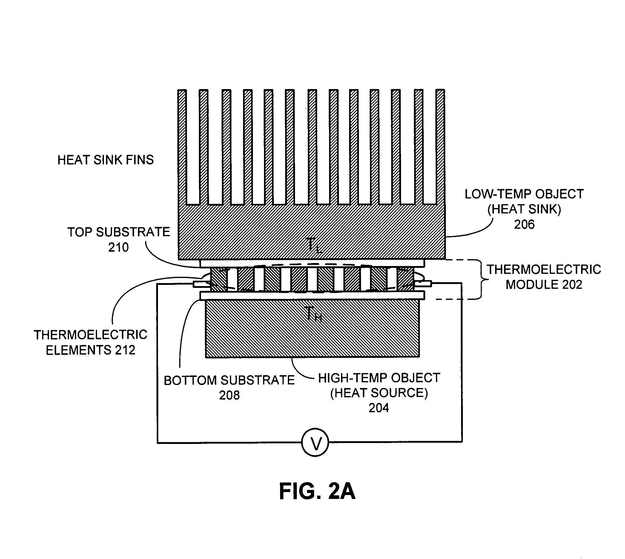
[0010]One embodiment of the present invention provides a system that cools integrated circuit (IC) chips within a computer system. During operation, the system converts heat generated by a heat-generating-device within the computer system into thermoelectric power. The system then supplies the thermoelectric power to an IC chip as a cooling power to reduce the operating temperature of the IC chip, thereby recycling wasted energy within the computer system.
[0013]In a further variation, the system increases the temperature difference by reducing the temperature of the second temperature reference.
[0014]In a further variation, the system reduces the temperature of the second temperature reference by using heat pipes to reduce the temperature.

Problems solved by technology

These advances can be largely attributed to an exponential increase in the density and complexity of integrated circuits (ICs).
Unfortunately, in conjunction with this increase in computational power, power consumption and heat dissipation of ICs has also increased dramatically.
Consequently, some power-demanding system components, such as a CPU or a graphics processing unit (GPU), can quickly reach unsafe operating temperatures.
Meanwhile, companies that operate servers are experiencing soaring energy costs because of the ever-increasing power consumption of the servers.
Unfortunately, conventional cooling techniques require additional electrical power and therefore increase power consumption problems.
However, this approach may significantly restrict computational power and other aspects of server performance.

Method used


Image

  • Method and apparatus for cooling integrated circuit chips using recycled power
  • Method and apparatus for cooling integrated circuit chips using recycled power
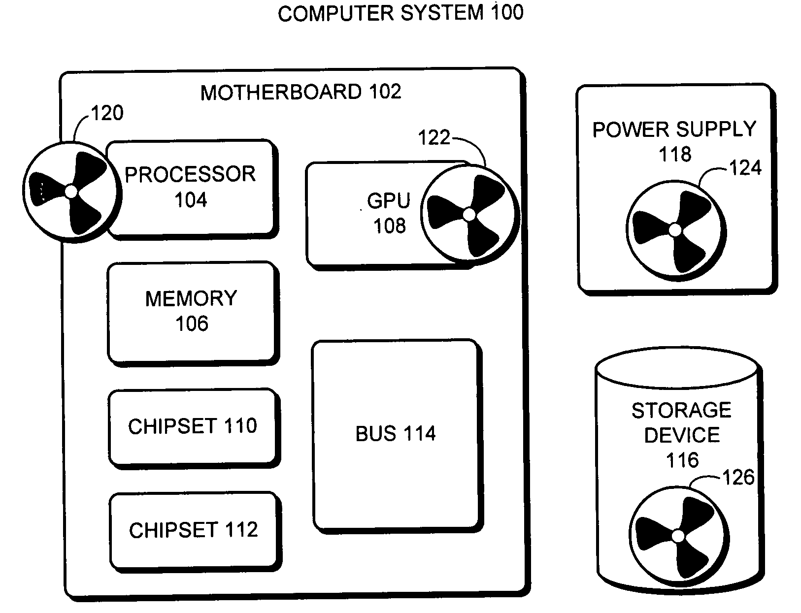
  • Method and apparatus for cooling integrated circuit chips using recycled power

Examples


Embodiment Construction

[0031]The following description is presented to enable any person skilled in the art to make and use the invention, and is provided in the context of a particular application and its requirements. Various modifications to the disclosed embodiments will be readily apparent to those skilled in the art, and the general principles defined herein may be applied to other embodiments and applications without departing from the spirit and scope of the present invention. Thus, the present invention is not limited to the embodiments shown, but is to be accorded the widest scope consistent with the claims.

Overview

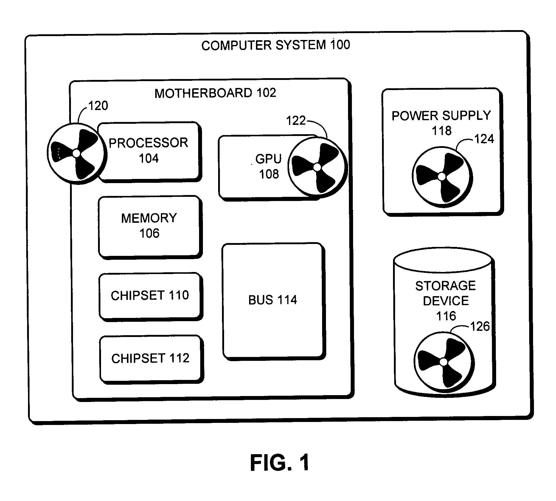
[0032]As processor speeds continue to increase in modern computer systems, a large amount of heat is being generated. Some heat sources in computer systems include: the CPU, the GPU, the power supply, and the hard disk drive (HDD). This heat is generally considered to be waste heat and considerable efforts have been taken to effectively remove this heat from these heat sources.

[0033]O...


PUM


Abstract

One embodiment of the present invention provides a system that cools integrated circuit (IC) chips within a computer system. During operation, the system converts heat generated by a heat-generating-device within the computer system into thermoelectric power. The system then supplies the thermoelectric power to an IC chip as a cooling power to reduce the operating temperature of the IC chip, thereby recycling wasted energy within the computer system.

Description

BACKGROUND[0001]1. Field of the Invention[0002]The present invention relates to techniques for improving energy efficiency within computer systems. More specifically, the present invention relates to a method and an apparatus that recycles heat dissipated within a computer system and converts the heat into cooling power for integrated circuit (IC) chips within the same computer system.[0003]2. Related Art[0004]Rapid advances in computing technology presently make it possible to perform trillions of operations each second on data sets as large as a trillion bytes. These advances can be largely attributed to an exponential increase in the density and complexity of integrated circuits (ICs). Unfortunately, in conjunction with this increase in computational power, power consumption and heat dissipation of ICs has also increased dramatically.[0005]Specifically, high-end computer servers can easily generate 20 kilowatts or more heat. Consequently, some power-demanding system components, s...

Claims


Application Information

Patent Timeline
IPC IPC(8): F25B21/02
CPCH01L23/38H01L25/165H01L2224/16225H01L2224/16227H01L2224/73253H01L35/00H10N10/00
Inventor OUYANG, CHIENGROSS, KENNY C.
Owner SUN MICROSYSTEMS INC
Learn More