
Energy Assisted Medical Devices, Systems and Methods

Inactive Publication Date: 2008-09-18
MEDRAD INC.
View PDF21 Cites 254 Cited by
  • Summary
  • Abstract
  • Description
  • Claims
  • Application Information

AI Technical Summary

Benefits of technology

[0036]In one embodiment, the surface of the first effector is a forward surface thereof. The forward surface of the first effector can be rough or abrasive. In general, a rough surface is marked by inequalities, ridges, or projections on the surface. The roughness or abrasiveness assists in “gripping” of tissue contacted by the surfaces so as to provide resistance to movement of the tissue relative to the forward surface.
[0041]In another aspect, the present invention provides a needle for sampling tissue including a first tubular structure and a vibrational coupler that couples rotational energy into the first tubular structure. The vibrational energy is suitable to penetrate tissue at the leading edge of the first tubular structure. The device further includes a second tubular structure positioned inside the first tubular structure, such that cut tissue passes into the second tubular structure and is protected from the effect of the rotational energy of the first tubular structure.
[0043]In another aspect, the present invention provides a needle system including a needle in operative connection with a syringe and an actuator in operative connection with the needle. The actuator is adapted to energize to the needle to assist in penetrating tissue. The needle can, for example, be connected to the syringe by a hub, wherein the hub allows relative motion between the needle and the syringe. The needle and the syringe can both be energized. In one embodiment, the actuator is in operative connection with a cradle in which a needle and syringe are insertable to energize the needle.
[0046]In a further aspect, the present invention provides a device for penetrating tissue including a nonlinear penetrator. The nonlinear penetrator includes at a forward end thereof at least a first effector. The device further includes at least one actuator in operative connection with the first effector. The actuator is adapted to cause motion of the first effector. The penetrator can be curved with a curve of a predetermined shape. The curve can have a constant radius of curvature or a varying radius of curvature. The penetrator can be curved in a simple or a complex manner. As used herein, the term “complex” refers to a curved section that curves in more than one direction or more than one plane. In one embodiment, the penetrator is flexible. The device can further include a mechanism to direct the penetration of the penetrator.
[0049]In still a further embodiment, the present invention provides a blunt needle including at least one effector that does not readily penetrate tissue and at least one actuator in operative connection with the effector that when energized enables or enhances the ability of the effector to penetrate tissue. The needle can contain a conduit such that fluid can be delivered to the tissue or material removed from the tissue.
[0050]In general, the energy assisted devices and systems of the present invention can be used in practically any medical procedure requiring penetration, hole boring or incision of tissue including, for example, biopsies of both soft and hard internal tissue; removal of tissue for therapy (for example, cataract removal); cauterization, incision (that is, surgery), needle access to veins, arteries, or other blood vessels for blood testing (including small sample blood testing as, for example, practiced by diabetics) aspiration, drainage access, gastrostonomy, chemical or RF ablation, sensor access to tissue and drug delivery to target tissue. Several advantages are provided over common instruments (including needles) currently used in such procedures. In general, these advantage are afforded by at least partially decoupling the penetrating or cutting action of the devices of the present invention from the forward force applied thereto. For example, smaller needles can be used, less push force is require, less “tug” force is felt by the patient, there is less of a tendency of deflection from the desired path, a curved path can be followed, the path can be changed during insertion, and there is less bleeding and damage to tissue. Patient pain can further be reduced with the devices of the present invention by, for example, local injection of an anesthetic, local affecting of nerves via applied electrical energy, local affecting of nerves via applied vibrational energy, air exclusion and / or the tissue penetrating profile of the device.

Problems solved by technology

Traditionally, biopsy has required open surgery that requires longer recovery time and typically involves the complications of pain and scarring.
Often biopsy procedures are uneventful.
This rebound or over penetration is a significant limitation to current robotic needle biopsy processes.
A similar problem occurs when a doctor tries to insert a trocar into the abdomen.
There is a risk of over penetration and damage of internal organs given the force that the doctor must exert on the trocar for it to penetrate the tough abdominal wall.
The ultrasonic energy is sufficiently intense that it disrupts the cell and tissue structure, with or without sufficient heat to cauterize the hole.
This can lead to a needle not following a straight path through the tissue.
A significant biopsy risk in the abdomen is hemorrhage as a result of cutting a significant blood vessel as the needle is inserted.
In addition, there are a number of lesions near the rib cage that cannot be accessed with straight biopsy needles.
In many parts of the body, there is a risk of severing nerves.
In the facial area this can lead to permanent paralysis and disfigurement.
Biopsying hard tissue or through hard tissue (to, for example, biopsy bone or the bone marrow) is especially difficult because of the stiffness of hard tissue.
Side cutting spring loaded biopsy needles like the Quick-Core made by Cook, Inc of Bloomington, Ind. have the drawback that a solid needle moves through the target tissue and out the other side, possibly displacing or seeding tumor cells into adjacent healthy tissue.
The challenges discussed above in relation to biopsy also occur with needle aspiration or drainage procedures.
The difficulty in gaining access to a patient's vein include piercing the tough vein wall, with the vein having the tendency to move from side to side, and potentially piercing through the back side of the vein given the jerk or momentum created by the high force required for initial penetration.
Pushing the needle through the tissue is difficult.
Even with local anesthetics, patients feel the pull and are uncomfortable or concerned.
This increases the difficulty of moving through the tissue and trauma to the patient.
One of the challenges in these uses of needles is to avoid coring, that is cutting a plug from the rubber stopper or other material that then lodges in the open lumen of the needle or moves in the fluid with the risk of being injected into the patient.
In all the uses describe above, accidental needle stick injuries are a serious hazard for health care workers and patients.
Often this action is forgotten or improperly executed, resulting in increased risk of injury.
Although energy other than manual energy (such as ultrasonic energy) has been applied to various medical instruments as discussed above, there has little progress in developing an energy assisted medical needle.

Method used


Image

  • Energy Assisted Medical Devices, Systems and Methods
  • Energy Assisted Medical Devices, Systems and Methods
  • Energy Assisted Medical Devices, Systems and Methods

Examples


Embodiment Construction

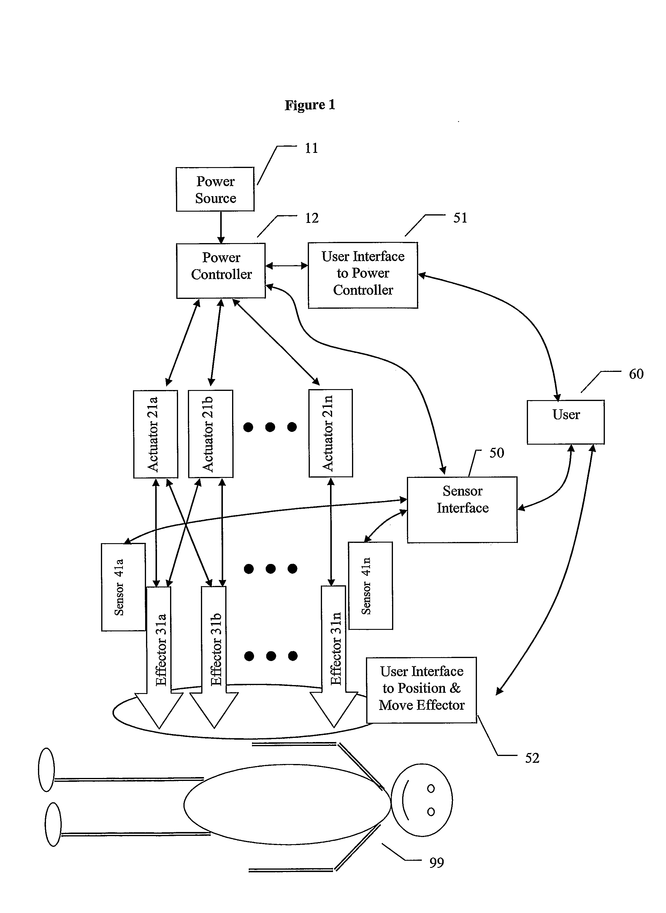
[0068]The energy assisted systems of the present invention can be used in connection with a number of medical devices and / or procedures. However, the systems of the present invention are discussed primarily herein in connection with representative embodiments of energy assisted “needles”. FIG. 1, for example, illustrates a block diagram of an energy assisted needle system of the present invention that will be used to discuss the general functionality of various embodiments of energy assisted needles of the present invention. As used herein, the term “needle” refers to relatively slender instruments that can be used to penetrate, and includes instruments having a passage or channel for introducing material into or removing material from the body parenterally. In common language, needles tend to be sharp and rigid whereas catheters are non-cutting and usually soft and flexible. With energy assistance, the distinction blurs because soft materials (such as the materials used in catheter...


PUM


Abstract

A device for penetrating tissue and removing a biological sample includes a biological sampling element to remove a biological sample. The biological sampling element includes a passage therethrough. The device further includes a penetrator positioned within the passage. The penetrator is energized in a repetitive manner to assist in penetrating tissue. The biological sample element can be adapted to remove a tissue sample or a biological fluid sample (for example, blood). A device for penetrating tissue and positioning a tissue resident conduit (for example, a catheter), includes a tissue resident conduit (for example, a catheter) including a passage therethrough; and a penetrator in operative connection with the catheter. A device for inserting a tissue resident conduit includes at least one component that is energized during penetration to assist in penetrating tissue. In one embodiment, the tissue resident conduit is flexible and the energized component is positioned or a forward end of the tissue resident conduit. The device can further include a mechanism for directing the penetration of the tissue resident conduit. A needle for penetrating tissue includes a first effector including a surface and at least one actuator in operative connection with the first effector. The actuator is adapted to cause motion of the first effector such that tearing of tissue takes place in regions where there is close proximity of tissue to the surface of the first effector.

Description

CROSS-REFERENCE TO RELATED APPLICATION[0001]This application claims benefit of U.S. Provisional Patent Application Ser. No. 60 / 552,660, filed Mar. 11, 2004, the disclosure of which is incorporated herein by reference.BACKGROUND OF THE INVENTION[0002]The present invention relates generally to energy assisted devices, systems and methods, and particularly, to energy assisted medical needles, to medical needles systems and to methods of inserting needles into tissue with the assistance of energy.[0003]A biopsy is a medical procedure that retrieves a piece of tissue from a patient for examination by a pathologist to make or to confirm a diagnosis with a high degree of certainty. The degree of certainty in the diagnosis is dependent upon obtaining a sample of the suspect tissue that is of sufficient quality for the diagnosis to be made.[0004]There are three types of biopsies including, surgical biopsies, endoscopic biopsies, and needle biopsies. As it is desirable to cause the patient as...

Claims


Application Information

Patent Timeline
IPC IPC(8): A61H1/00A61B10/02A61M25/06A61B5/15
CPCA61B2010/0208A61B10/0233
Inventor UBER, ARTHUR E.GRIFFITHS, DAVID M.HIRSCHMAN, ALAN D.
Owner MEDRAD INC.
Learn More