
Outboard motor

a technology for outboard motors and propellers, applied in vessel parts, vessel construction, gearing, etc., can solve the problems of large space required for its installation, large pitch propellers need a larger driving torque during acceleration, and complex structure, and achieve the effect of large reduction of gear ratio and simple structur

Active Publication Date: 2008-09-18
YAMAHA MOTOR CO LTD
View PDF14 Cites 11 Cited by
  • Summary
  • Abstract
  • Description
  • Claims
  • Application Information

AI Technical Summary

Benefits of technology

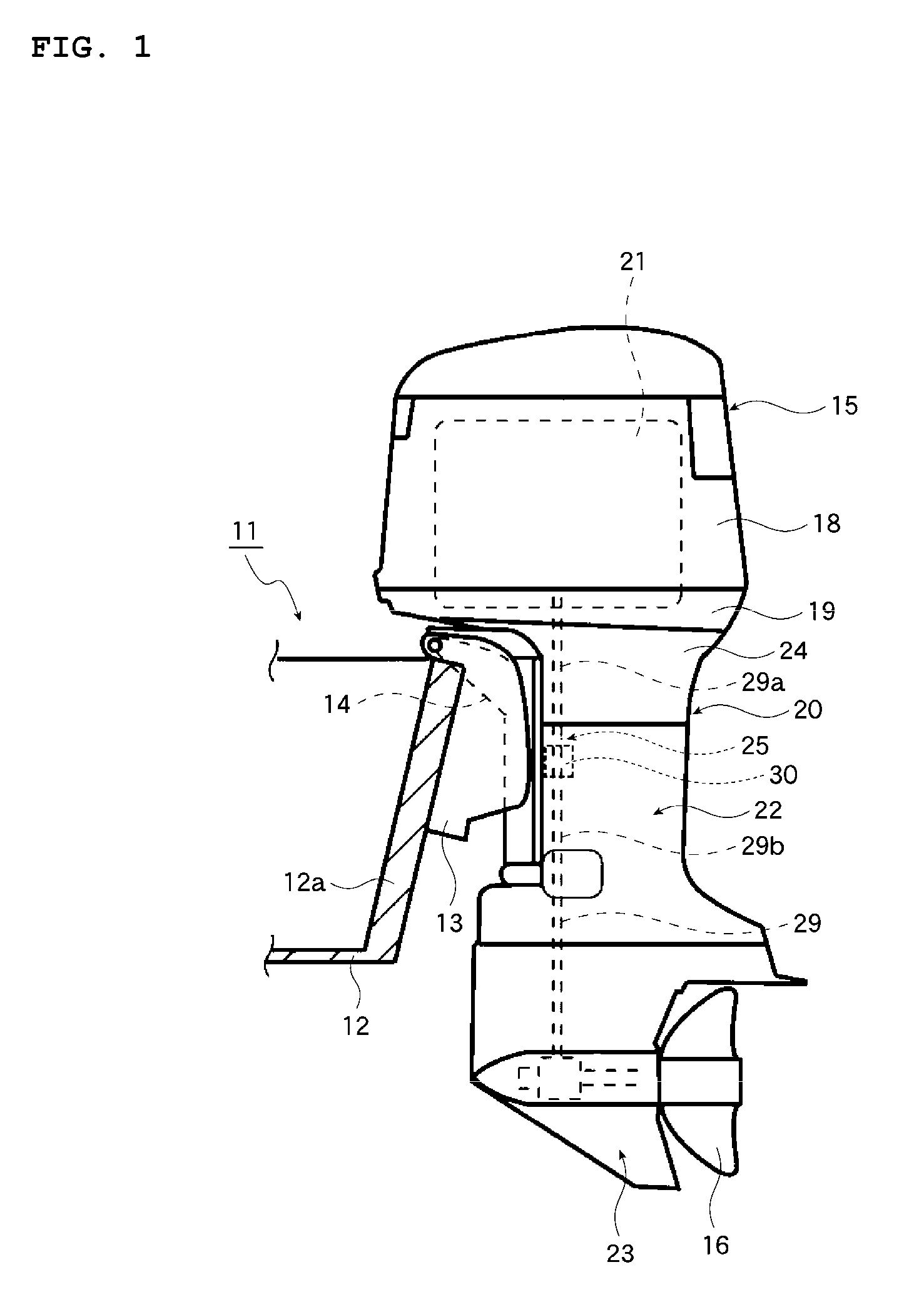
[0012]In order to overcome the problems described above, preferred embodiments of the present invention provide an outboard motor having a transmission unit that is compact and simple in structure, and at the same time allows a large reduction gear ratio.

Problems solved by technology

Thus, it is a complicated structure and a large space is required for its installation.
But, a large pitch propeller needs a larger driving torque during acceleration.
Solutions such as providing a turbocharger that adds torque in the low speed range is not very useful when a large pitch propeller is used for the improvement of cruising performance.

Method used


Image

  • Outboard motor
  • Outboard motor
  • Outboard motor

Examples


second preferred embodiment

[0085]FIG. 13 shows the second preferred embodiment of the present invention. The structure in the lower portion of the outboard motor 15 is shown in FIG. 13. The structure in the upper portion extending upward in FIG. 13 is preferably substantially the same as the first preferred embodiment having the transmission planetary gear train 35 and the shifting planetary gear train 36.

[0086]The second preferred embodiment differs from the first preferred embodiment in that a pair of propellers 45, 46 are arranged to rotate in opposite directions with respect to each other.

[0087]In the second preferred embodiment, a driven gear 47 in the front portion is engaged with the first propeller shaft 48 to rotate integrally with the first propeller shaft 48, and the first propeller shaft 48 extends toward the second propeller 46 to engage the second propeller 46 with the first propeller shaft 48. Also, a driven gear 50 in the rear portion is engaged with a second propeller shaft 49 to rotate integ...


PUM


Abstract

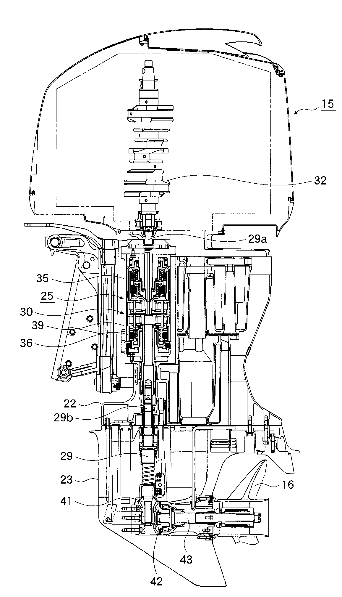
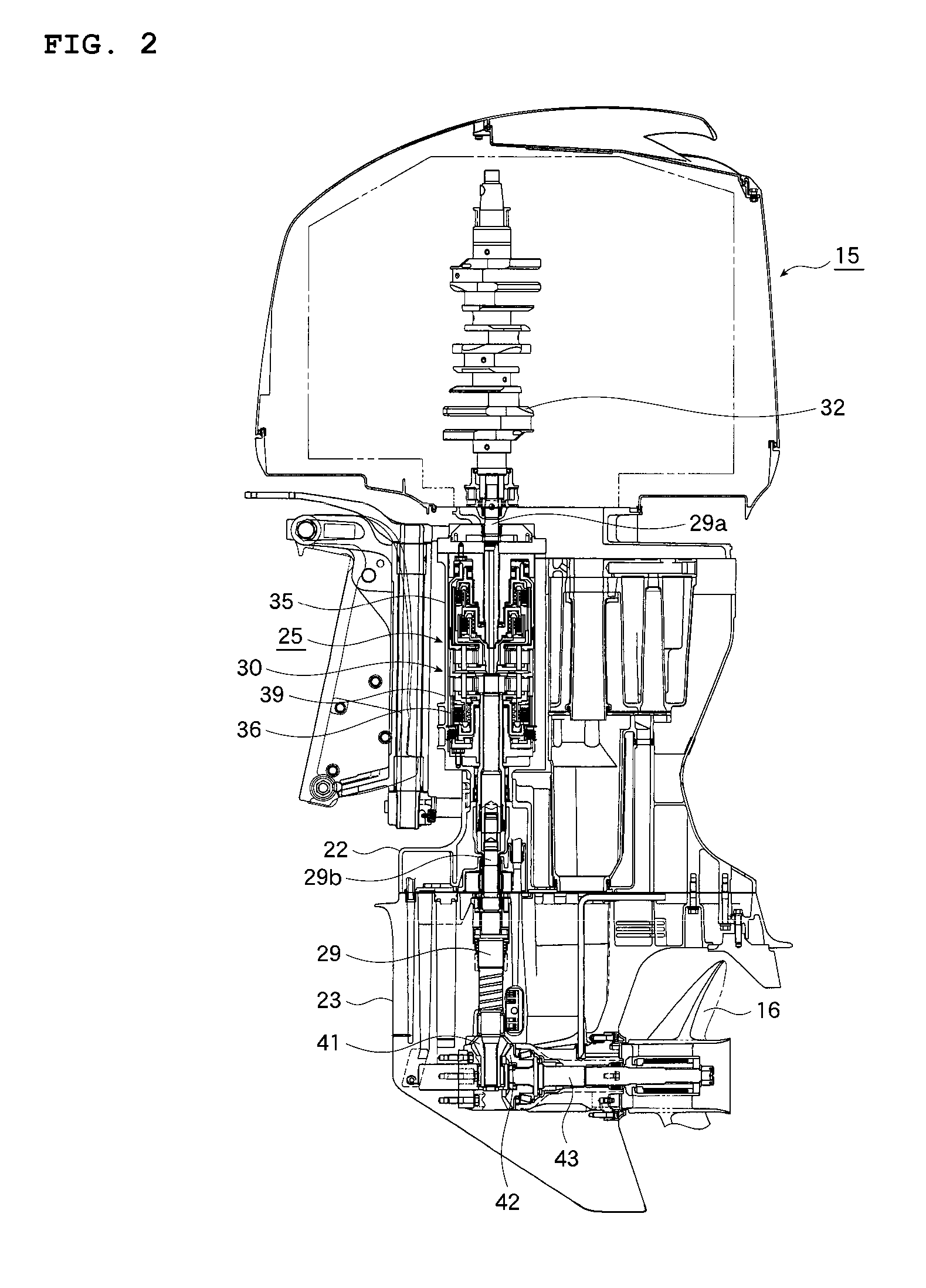
A power transmission mechanism transferring a power output from an engine to a propeller includes a transmission planetary gear train that transforms the output power of the engine before it is transferred to the propeller. The transmission planetary gear train includes a transmission sun gear, a transmission double planetary gear set, and a transmission internal gear, in which the transmission sun gear is connected via the first clutch to the input end shaft extending into the engine, and the transmission sun gear is also connected via the second one-way clutch to the housing. In addition, the transmission double planetary gear set is connected via the second clutch to the input end shaft extending into the engine, and the transmission double planetary gear set is also connected via the first one-way clutch to the housing. Further, the transmission internal gear is connected to the output end shaft extending toward the propeller.

Description

BACKGROUND OF THE INVENTION[0001]1. Field of the Invention[0002]The present invention relates to an outboard motor having a power transmission mechanism to transfer an output power from an engine to a propeller, and more particularly to an outboard motor having a speed change gear structure contained in the transmission mechanism to transform the output power of the engine supplied to the propeller.[0003]2. Background Art[0004]One conventional type of such a mechanism for an outboard motor is described in JP-B-2686517, for instance. JP-B-2686517 discloses an outboard motor in which a first drive shaft is connected to the output shaft of the engine, the second drive shaft is disposed coaxially with the first drive shaft by way of a transmission unit, and a reduction and reversing gear mechanism is arranged to transfer the thrust received by the second drive shaft to a propeller shaft.[0005]The transmission unit is composed of first and second planetary gear trains, with the first and...

Claims


Application Information

Patent Timeline
IPC IPC(8): F16H3/44F01P5/10B63H23/16
CPCB63H5/10B63H20/14B63H20/20B63H23/04F16H2200/2046B63H2023/0283F16H3/64F16H2200/0039F16H2200/2007B63H23/06
Inventor OKABE, YOSHIHIKO
Owner YAMAHA MOTOR CO LTD
Learn More