Method for determining the gas volume flow in gas recirculation at a filling station
- Summary
- Abstract
- Description
- Claims
- Application Information
AI Technical Summary
Benefits of technology
Problems solved by technology
Method used
Image
Examples
Embodiment Construction
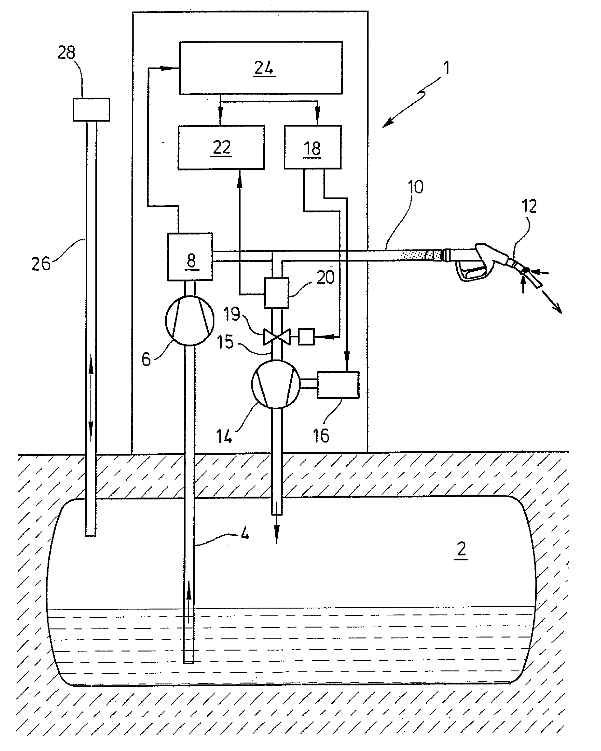
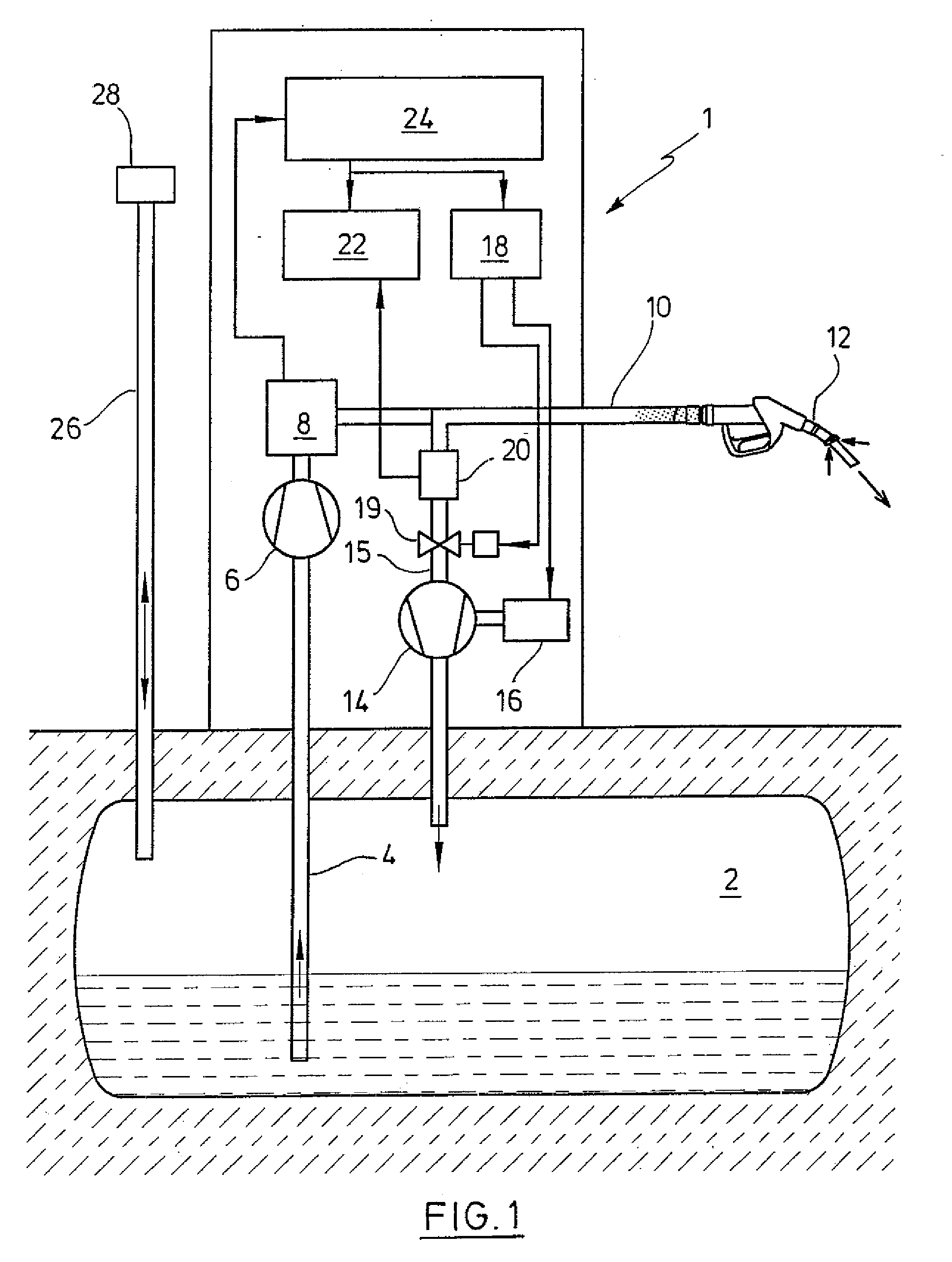
[0040]FIG. 1 illustrates diagrammatically a petrol pump 1 at a filling station, together with the most important parts, including the components of a gas recirculation system and its monitoring, which are arranged in it or are assigned to the petrol pump 1.
[0041]When the petrol pump 1 is in operation, fuel passes out of an underground storage tank 2 via a fuel line 4 and, conveyed by a fuel pump 6, through a fuel throughflow meter 8 serving to measure the fuel volume flow, and a petrol pump hose 10 to a petrol pump valve 12, from which the fuel is introduced into the tank of a motor vehicle, as indicated by large arrows. At the same time, the fuel vapours (gas, which, as a rule, is a mixture of hydrocarbons and air), which stand above the liquid fuel in the tank of the motor vehicle, are sucked away, this being indicated by the two small arrows at the petrol pump valve 12. This gas is sucked in by a gas pump 14 via a separate line routed within the petrol pump hose 10 and passes thr...
PUM
 Abstract
Description
Claims
Application Information
 - Generate Ideas
- Intellectual Property
- Life Sciences
- Materials
- Tech Scout
- Unparalleled Data Quality
- Higher Quality Content
- 60% Fewer Hallucinations
Browse by: Latest US Patents, China's latest patents, Technical Efficacy Thesaurus, Application Domain, Technology Topic, Popular Technical Reports.
© 2025 PatSnap. All rights reserved.Legal|Privacy policy|Modern Slavery Act Transparency Statement|Sitemap|About US| Contact US: help@patsnap.com


