Rolling Bearing

Inactive Publication Date: 2008-08-14
NTN CORP
View PDF6 Cites 3 Cited by
  • Summary
  • Abstract
  • Description
  • Claims
  • Application Information

AI Technical Summary

Benefits of technology

[0003]In recent years, there are tendencies of downsizing and increasing power output of a portion in which the rolling bearing is used such as a transmission of an automobile, and a viscosity of a lubricating oil tends to be lower. In other words, in a use environment of the rolling bearing, load and temperature are increasing. Thus, a lubrication environment has been changing to be severer for bearings than ever before. Separations of a surface originating type due to lubrication failure, reduction in fatigue life due to higher contact pressure, and separations under foreign matter contaminated environment tend to occur easily. In this case, it is required to enable enhancement of the life under any lubrication conditions such as low viscosity severe lubrication, the foreign matter contaminated environment, or detergent oil lubrication.
[0005]The rolling bearing according to an embodiment of the present invention includes at least on a surface of a rolling element innumerable minute concave recesses randomly formed. An average area of the recesses is in a range of 30 to 100 μm2, and Rymax is in a range of 0.4 to 1.0. At least on the surface of the rolling element, the innumerable minute concave recesses are randomly formed, thereby enhancing an oil film forming ability and realizing elongation in life even under conditions in which the oil film is extremely thin under the low viscosity and the lean lubrication. In particular, by setting the average area of the recesses in a range of 30 to 100 μm2 and Rymax in a range of 0.4 to 1.0, it is possible to prevent an oil film shortage even under the lean lubrication. As compared to the conventional product, it is possible to obtain the longer life even under the conditions in which the oil film is extremely thin.
[0006]At least one of an outer member, an inner member, and the rolling element constituting the rolling bearing has a nitrogen-enriched layer. An austenite grain size in the nitrogen-enriched layer may be in a range larger than a grain size No. 10. After forming the nitrogen-enriched layer, by setting the austenite grain size smaller so that the grain size number becomes larger than No. 11, the rolling fatigue life is significantly improved, thereby making it possible to obtain an excellent crack resistance and resistance to dimensional change by aging.

Problems solved by technology

Separations of a surface originating type due to lubrication failure, reduction in fatigue life due to higher contact pressure, and separations under foreign matter contaminated environment tend to occur easily.
However, effects thereof may not be exerted when an oil film is extremely thin under conditions of low viscosity and lean lubrication.

Method used


Image

  • Rolling Bearing
  • Rolling Bearing
  • Rolling Bearing

Examples


example 1

[0069]By using a JIS standard SUJ2 material (1.0 mass percent C—0.25 mass percent Si—0.4 mass percent Mn—1.5 mass percent Cr), the following tests were conducted, that is, (1) hydrogen amount measurement, (2) grain size measurement, (3) Charpy impact test, (4) breaking stress value measurement, and (5) rolling fatigue test. Table 1 shows results of those.

TABLE 4ConventionalcarbonitridingNormalSampleABCDEFtreatmentquenchingSecondary quenching780800815830850870——temperature (° C.)Hydrogen amount (ppm)—0.370.480.380.420.400.720.33Grain size (JIS)—1211.51130151010Charpy impact value—6.655.456.306.206.305.336.70(J / cm2)Breaking stress value—2840278025502850270023302770(MPa)Rolling fatigue life—5.44.23.52.92.83.11ratio (Lm)

[0070]Production history of each of the samples is described below.

[0071]The samples A to D (examples of the present invention): Carbonitriding treatment 850° C., and retention time 150 minutes. An atmosphere was given as a mixed gas of RX gas and an ammonia gas. In the ...

example 2

[0109]Next, an example 2 will be described. An X material, a Y material, and a Z material below were subjected to a series of tests. As a heat treatment material, JIS standard SUJ2 material (1.0 mass percent C—0.25 mass percent Si—0.4 mass percent Mn—1.5 mass percent Cr) was used commonly for each of the X to Z materials. Manufacturing histories of the X to Z materials are as follows.[0110]X material (comparative example): Only normal quenching (carbonitriding treatment is not performed).[0111]Y material (comparative example): Quenching was performed after the carbonitriding treatment without any other process (conventional carbonitriding quenching). Carbonitriding treatment temperature 845° C., and retention time 150 minutes. An atmosphere of the carbonitriding treatment was RX gas+ammonia gas.[0112]Z material (example of the present invention): A bearing steel which underwent the heat treatment pattern of FIG. 12. Carbonitriding treatment temperature 845° C., and the retention tim...

example 3

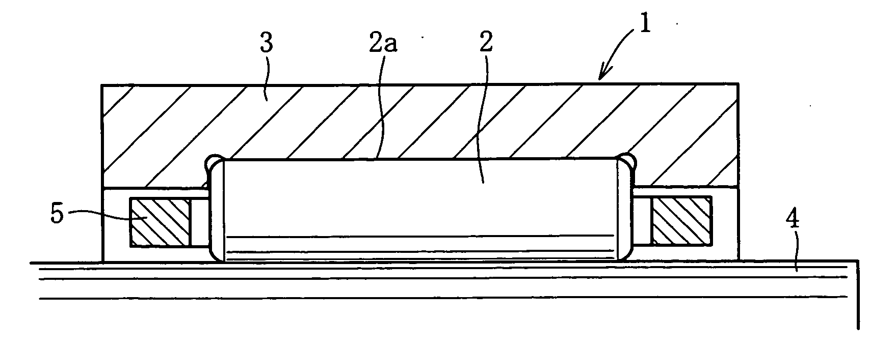
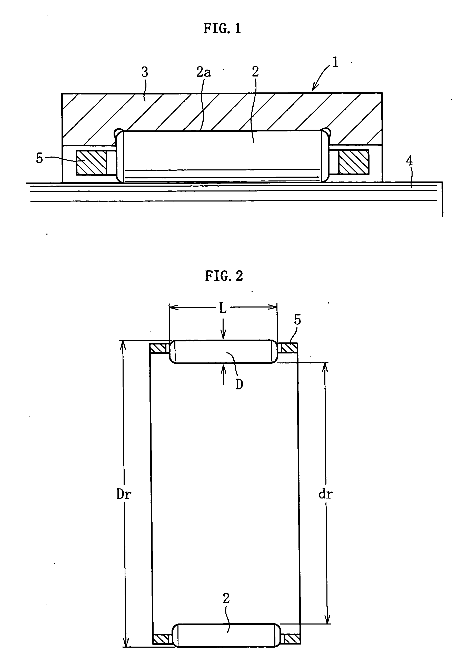
[0128]Table 11 shows results of a test conducted for a relationship between the nitrogen content and the rolling life under a condition of foreign matter incorporation. In this test, the tapered roller bearing shown in FIG. 8 is used. In examples 1 to 5, all the outer race 13, the inner race 14, and the tapered rollers 16 are manufactured while being applying with the heat treatment pattern shown in FIG. 12. Further, on the surface of the tapered roller, the innumerable minute concave recesses shown in Table 1 and Table 2 are randomly formed. Note that, a comparative example 1 is a normal quenched product, and a comparative example 2 is a normal carbonitrided product. A comparative example 3 shows a case where there is an excess of only a nitrogen amount although the same treatment as that of the examples of the present invention is applied. Test results are as follows.[0129]Test bearing: Tapered roller bearing 30206 (inner / outer races and rollers are made of high-carbon chromium be...


PUM


Abstract

At least on a surface of a rolling element of a rolling bearing, innumerable minute concave recesses are randomly formed. An average area of the recesses is in a range of 30 to 100 μm2, and Rymax is in a range of 0.4 to 1.0.

Description

TECHNICAL FIELD[0001]The present invention relates to a rolling bearing, which can be applied to, for example, a roller bearing used for a shaft supporting portion as a transmission of an automobile.BACKGROUND ART[0002]JP-A-02-168021 and JP-A-06-42536 each disclose a rolling bearing in which a surface of a rolling element is provided with minute irregularities formed thereon to improve an oil film forming ability. In this conventional technique, as a countermeasure for a damage due to poor lubrication, such as a peeling damage of a roller bearing, there are provided recesses each having a minute concave shape in rolling contact surfaces of rollers and / or raceway surfaces of inner and outer races. When a surface roughness is expressed by a parameter Rqni, a value of a ratio Rqni (L) / Rqni (C) between an axial surface roughness Rqni(L) and a circumferential surface roughness Rqni(C) becomes 1.0 or less, and a parameter Sk value of the surface roughness is set to be −1.6 or less, thereb...

Claims


Application Information

Patent Timeline
IPC IPC(8): F16C33/62
CPCF16C33/32F16C33/6651F16C33/34F16C2240/54F16C33/62
Inventor TSUJIMOTO, TAKASHIFUKAMI, RINO
Owner NTN CORP
Why Eureka
Try Eureka