Selection method, selection system, selection device and recording medium
a selection system and selection method technology, applied in the field of selection methods, selection systems, selection devices and recording media, can solve the problems of limiting the memory capacity, affecting the efficiency of the selection system, and the processing burden of the downstream computer, so as to reduce the communication traffic between dealers and achieve rapid logistics management
- Summary
- Abstract
- Description
- Claims
- Application Information
AI Technical Summary
Benefits of technology
Problems solved by technology
Method used
Image

Examples
embodiment 1
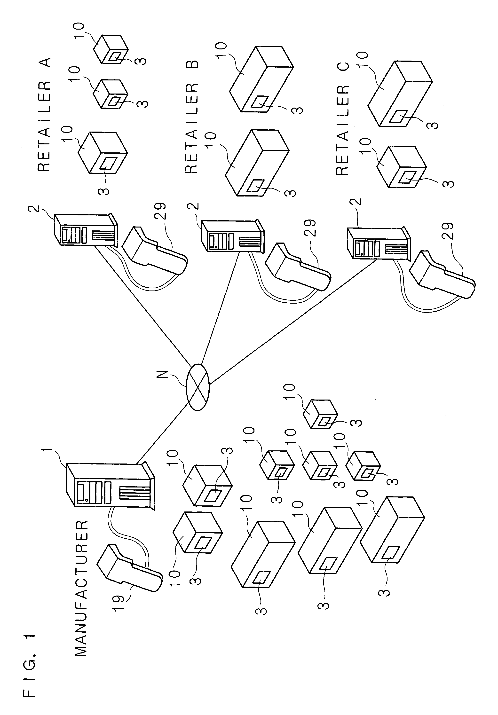
[0055]The following will explain an embodiment of the present invention with reference to the drawings. FIG. 1 is a schematic view showing an outline of a selection system according to the present invention. Although the following explains the embodiment by giving an example in which wireless tags are attached to products, such as the main body of a personal computer, a display or a memory, this is merely one example and the embodiment is not limited to this. The selection system comprises a wireless tag 3 (hereinafter referred to as the RF tag 3, RFID: Radio Frequency Identification tag, RF IC tag) attached to a product such as a main body of personal computer, a selection device 1, information processing devices 2, 2, 2 . . . connected to the selection device 1 through a communication network N such as the Internet, a reader / writer 19 and a reader / writer 29 . . . as reading devices for reading the information stored on RF tags 3 and writing devices for writing information to RF ta...
embodiment 2
[0088]Embodiment 2 relates to a mode in which the priority ranking is changed based on the correlation between product information. FIG. 10 is a block diagram showing the hardware structures of the upstream server 1 and RF tag 3 according to Embodiment 2. In addition to the structure of Embodiment 1, a correlation value file 156 is stored in the memory unit 15. Note that although a similar correlation value file is stored in the downstream server 2, illustration thereof is omitted.
[0089]FIG. 11 is an explanatory view showing the record layout of the correlation value file 156. The CPU 11 refers to the history DB 153 at predetermined intervals and performs the process of changing the priority ranking stored in the priority ranking file 155. In the correlation value file 156, combinations of product information and partner product information for calculation of correlation values are stored in order of priority rankings, and a correlation value between product information and partner ...
embodiment 3
[0108]Embodiment 3 relates to a mode in which predetermined information is transmitted from the downstream server 2 to the upstream server 1 in order to modify the priority rankings. FIG. 16 is an explanatory view showing the hardware structure of the downstream server 2 according to Embodiment 3. In addition to the structure of Embodiment 1, a transmission request history file 256 is stored in the memory unit 25 of the downstream server 2 of Embodiment 3. Whenever the CPU 21 of the downstream server 2 sends a transmission request for product information, it stores the history in the transmission request history file 256.
[0109]FIG. 17 is an explanatory view showing the record layout of the transmission request history file 256. The transmission request history file 256 includes the ID field, Product Name field, Item field, Transmission Request Date field, and Response Time field. In the ID field, the ID of a RF tag corresponding to product information for which the transmission requ...
PUM
 Abstract
Description
Claims
Application Information
 - R&D
- Intellectual Property
- Life Sciences
- Materials
- Tech Scout
- Unparalleled Data Quality
- Higher Quality Content
- 60% Fewer Hallucinations
Browse by: Latest US Patents, China's latest patents, Technical Efficacy Thesaurus, Application Domain, Technology Topic, Popular Technical Reports.
© 2025 PatSnap. All rights reserved.Legal|Privacy policy|Modern Slavery Act Transparency Statement|Sitemap|About US| Contact US: help@patsnap.com