
Spin microscope based on optically detected magnetic resonance

a magnetic resonance and spin microscope technology, applied in the direction of mechanical measurement arrangements, mechanical roughness/irregularity measurements, instruments, etc., can solve the problem of limiting the lateral resolution of odmr to the size of the light spot, using stm and afm devices, and not being able to provide information about three-dimensional structures

Inactive Publication Date: 2008-07-24
THE UNITED STATES AS REPRESENTED BY THE DEPARTMENT OF ENERGY
View PDF12 Cites 7 Cited by
  • Summary
  • Abstract
  • Description
  • Claims
  • Application Information

AI Technical Summary

Benefits of technology

The patent describes a new way to improve the resolution of magnetic force resonance microscopy (MFRM) using optically detected magnetic resonance (ODMR). This is achieved by using a photoluminescent nanoparticle located at the tip of a scanning probe, which exhibits optically detected magnetic resonance in the sample material. The resolution of this method is determined by the size of the nanoparticle, which can be in the range of 1-10 nanometers or even of Angstrom scale. The described spin microscope has demonstrated nanoscale lateral resolution and single spin sensitivity for the AFM and STM embodiments. The invention has promising applications including spatial mapping of interfacial magnetism in nano-structures, imaging of three-dimensional bio-molecular structures, and non-demolition measurement of single spin state represented qubit in a quantum computer.

Problems solved by technology

Usually, STM and AFM devices are used for imaging of surface structures and cannot provide information about three-dimensional structures which are of the greatest interest in nano-technology, structural biology, bio-chemistry, and related fields of science.
The limitation of the lateral resolution of ODMR is related to the size of the light spot.
Another limitation of the ODMR technique is that the impaired electron has to be a part of a molecule, which absorbs or emits light.

Method used


Image

  • Spin microscope based on optically detected magnetic resonance
  • Spin microscope based on optically detected magnetic resonance
  • Spin microscope based on optically detected magnetic resonance

Examples


Embodiment Construction

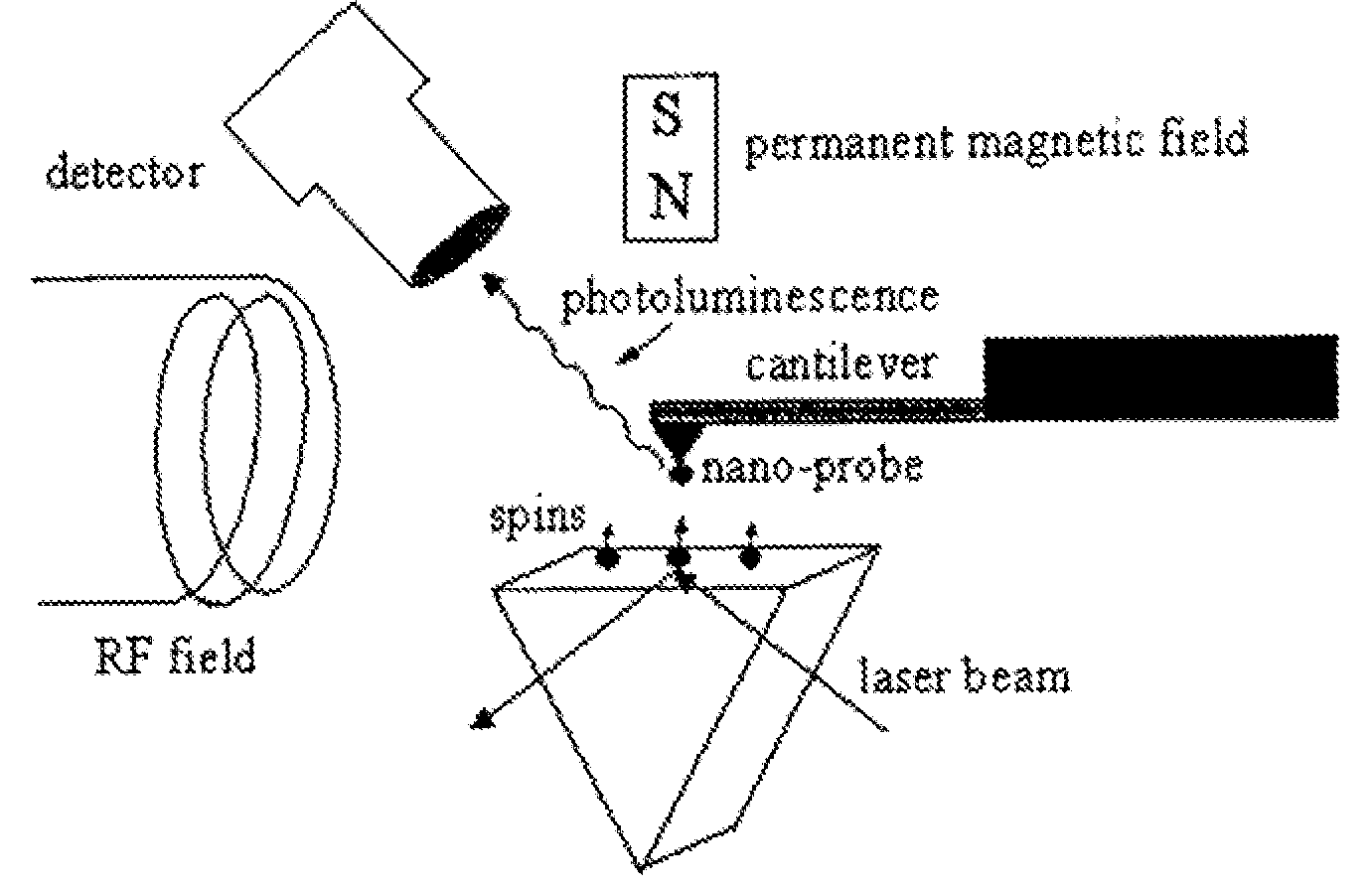
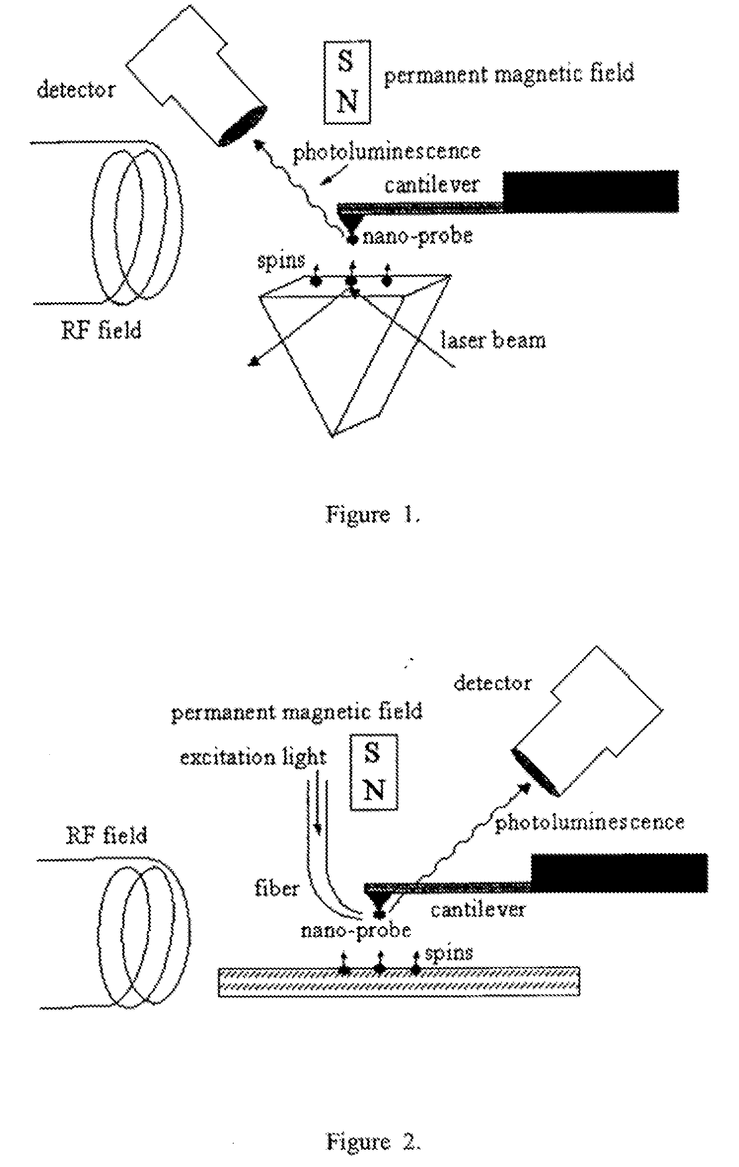
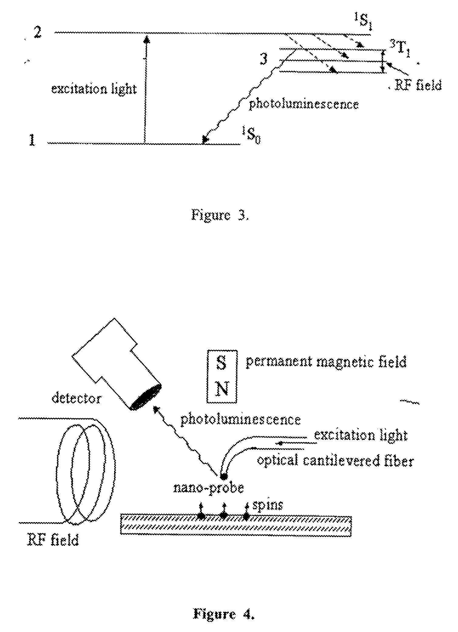
[0015]In the present invention a modification of the optically detected magnetic resonance (ODMR) technique is described which is free from the limitations of the conventional ODMR method. In this approach a photoluminescent nanoparticle 1 or other photoluminescent center located on the tip apex of a micro-cantilever 4 exhibits ODMR in the vicinity of unpaired electron spins 2 or nuclear magnetic moments in the sample 3. We have identified several approaches to this spin microscope based on ODMR, the general layouts of which are shown in FIGS. 1,3-5. FIG. 1 presents a design based on the apertureless scanning optical microscope, which exploits the highly sensitive atomic force microscope (AFM) tip modified by implanting a nano-size photoluminescent particle 1 in the apex of the tip. The sample 3 material to be observed is located in close proximity to the tip-on-cantilever system, and a permanent magnet 5 is placed nearby. A nearby radio-frequency (rf) coil 6 produces an oscillating...


PUM

PropertyMeasurementUnit
sizeaaaaaaaaaa
sizeaaaaaaaaaa
diameteraaaaaaaaaa

Abstract

The invention relates to scanning magnetic microscope which has a photoluminescent nanoprobe implanted in the tip apex of an atomic force microscope (AFM), a scanning tunneling microscope (STM) or a near-field scanning optical microscope (NSOM) and exhibits optically detected magnetic resonance (ODMR) in the vicinity of impaired electron spins or nuclear magnetic moments in the sample material. The described spin microscope has demonstrated nanoscale lateral resolution and single spin sensitivity for the AFM and STM embodiments.

Description

CROSS-REFERENCE TO RELATED APPLICATION[0001]This application claims priority from U.S. provisional application Ser. No. 60 / 560,979 filed on Apr. 12, 2004.STATEMENT REGARDING FEDERALLY SPONSORED RESEARCH OR DEVELOPMENT[0002]The U.S. Government has a paid-up license in this invention and the right in limited circumstances to require the patent owner to license others on reasonable terms as provided for by the terms of Contract No. W-7405-ENG-36 awarded by the U.S. Department of Energy and Los Alamos National Laboratory.BACKGROUND OF THE INVENTION[0003]1. Field of the Invention (Technical Field)[0004]The present invention relates to a scanning magnetic microscope based on optically detected magnetic resonance and embodiments thereof.[0005]2. Description of Related Art[0006]Significant progress in recent years in scanning tunneling microscopy (STM) and atomic force microscopy (AFM) have had a revolutionary impact in the direct imaging of atomic scale structure. Usually, STM and AFM devi...

Claims


Application Information

Patent Timeline
Patent Type & Authority Applications(United States)
IPC IPC(8): G01N23/00
CPCB82Y15/00B82Y25/00B82Y35/00G01Q30/02G01R33/10G01Q60/52G01Q70/18G01R33/0385G01Q60/02
Inventor BERMAN, GENNADY P.CHERNOBROD, BORIS M.
Owner THE UNITED STATES AS REPRESENTED BY THE DEPARTMENT OF ENERGY
Learn More