Boiler Apparatus

a technology of boilers and heat exchange tubes, which is applied in the direction of lighting and heating apparatus, steam boiler components, steam boilers, etc., can solve the problems of affecting the service life of economizers, and affecting the service life of steam boilers. , to achieve the effect of preventing damage to the boiler and the economizer, reducing the corrosion of heat exchange tubes, and reducing the risk of failur

Inactive Publication Date: 2008-07-10
MIURA COMPANY LIMITED
View PDF13 Cites 7 Cited by
  • Summary
  • Abstract
  • Description
  • Claims
  • Application Information

AI Technical Summary

Benefits of technology

[0009]It is an object of the present invention to suppress generation of corrosion in the heat transfer tubes of a boiler or an economizer under an influence of water.

Problems solved by technology

The heat transfer tubes are formed of a non-passive metal, such as carbon steel, so the portions of the heat transfer tubes coming into contact with the boiler water suffer damage due to corrosion attributable to the influence of the boiler water, which may fatally affect the service life of the steam boiler.
Since the heat-transfer tubes are formed of a non-passive metal, such as carbon steel, the portions of the heat transfer tubes coming into contact with supply water suffer damage due to corrosion caused under the influence of the supply water, which may fatally affect the service life of the economizer.
Corrosion of the heat transfer tubes is likely to occur in portions continuously kept in contact with supply water or boiler water.
For example, in a one-through boiler, which is a type of water tube boiler, the connecting portions between the heat transfer tubes and a lower header tend to undergo corrosion.
In the economizer, supply water constantly exists in the heat transfer tubes during operation of the boiler, so corrosion is likely to occur.
Generally speaking, when the water contains a lot of corrosion promoting ingredients, such as sulfate ions, chloride ions, or dissolved oxygen, and contains little corrosion suppressing ingredient, such as silica, the possibility of corrosion of the heat transfer tubes is high.
In addition to thinning corrosion, the heat transfer tubes are subject to local corrosion, which may cause minute perforation, thereby being damaged.
Here, the local corrosion is a boring-like corrosion occurring from the side where the heat transfer tubes and the water come into contact with each other toward the opposite side in a thickness direction, that is, a pitting occurring in a wall-thickness direction of the heat transfer tubes, which leads to damage of the heat transfer tubes in a short period of time.
In the heat transfer tubes, however, the water temperature at a portion where the supply water flows in, for example, at the connecting portion between the heat transfer tubes and the lower header, is relatively low, so concentration or boiling does not easily occur.
Thus, even when the concentration rate of the boiler water is controlled to be within a predetermined range, an increase in pH or deoxidation does not easily occur, which means corrosion may be generated.
On the other hand, in the economizer mentioned above, temperature rise of the supply water due to heat exchange with the exhaust gas is approximately 120° C. at the most, and the alkali ingredients in the supply water do not easily undergo thermal decomposition, nor does concentration take place.
That is, in the heat transfer tubes, the pH of the supply water does not increase, so, as compared with the case of the boiler, corrosion is more likely to be promoted.
Further, the interior of the heat transfer tubes is in a pressurized state, so boiling of the supply water does not take place, and the concentration of the dissolved oxygen is not reduced, so corrosion is likely to be promoted.

Method used


Image

  • Boiler Apparatus
  • Boiler Apparatus
  • Boiler Apparatus

Examples


first embodiment

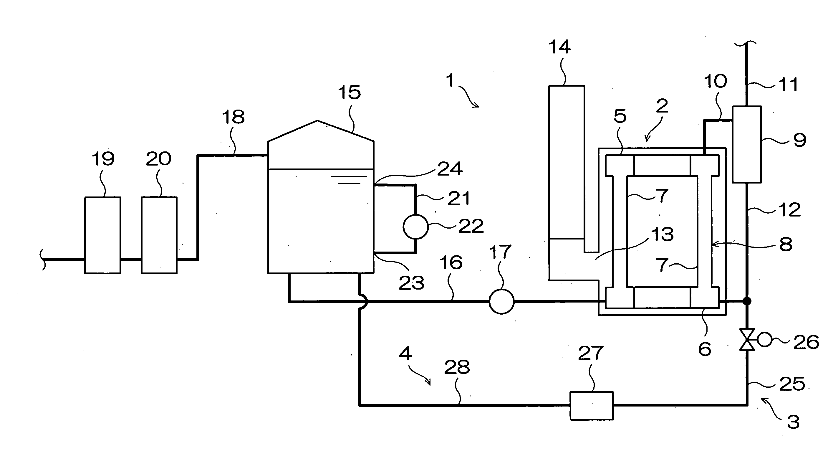
[0045]In the following, a first embodiment of the present invention will be described in detail with reference to the corresponding figure. FIG. 1 is a schematic diagram showing a construction of a boiler apparatus according to the first embodiment of the present invention. The boiler apparatus 1 is mainly equipped with a boiler 2, boiler water gathering means 3, and boiler water adding means 4.

[0046]The boiler 2 is a so-called multi-tubular water tube boiler, and is equipped with a boiler body 8 in which a large number of water tubes (heat transfer tubes) 7 are arranged upright between an upper header 5 and a lower header 6. The upper header 5 is connected to a water separator 9 through a steam supply channel 10, and the upper portion of the water separator 9 is connected to a load apparatus (not shown) through steam piping 11. To recover separated water, the lower portion of the water separator 9 is connected to the lower header 6 through a down corner 12. Further, connected to th...

second embodiment

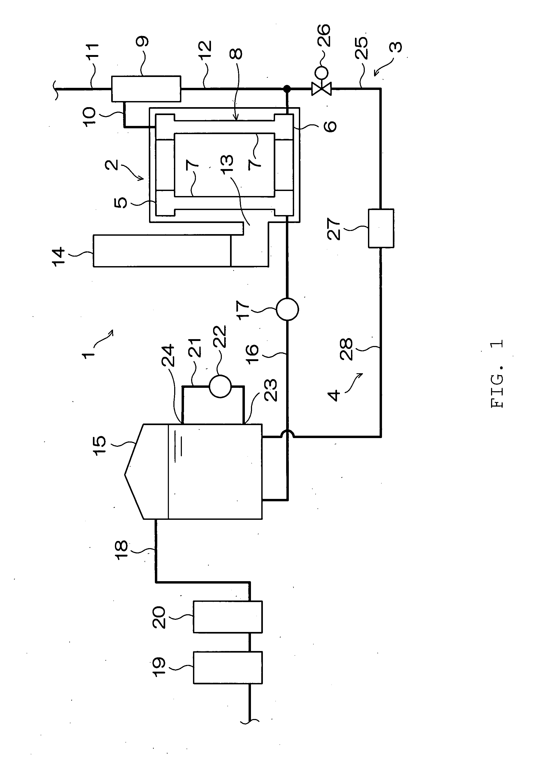
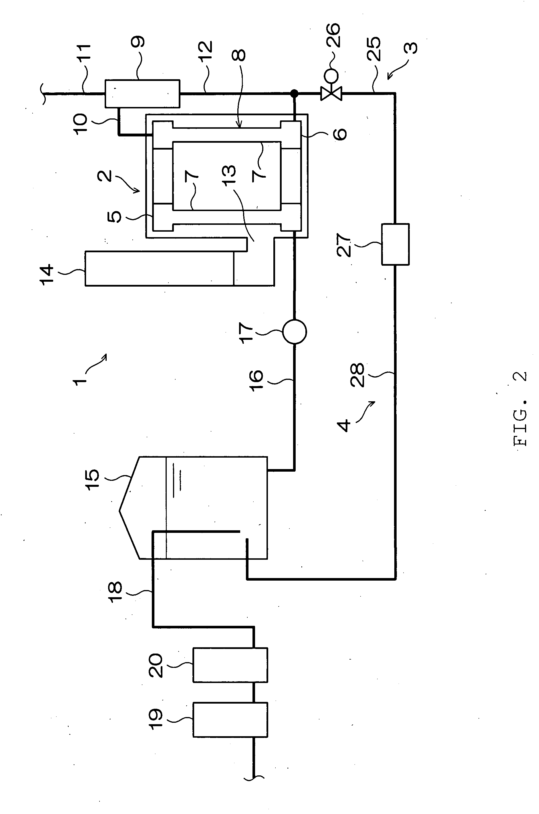
[0056]Next, the second embodiment of the present invention will be described in detail with reference to the corresponding figure. The second embodiment is a modification of the first embodiment of the present invention. FIG. 2 is a schematic diagram showing a construction of a boiler apparatus according to the second embodiment of the present invention. In FIG. 2, components that are the same as those of the first embodiment of the present invention are indicated by the same reference numerals, and a detailed description of such components will be omitted.

[0057]In the second embodiment of the present invention, the water supply channel 18 extends toward the bottom of the supply water tank 15. That is, the supply water that has undergone treatment at the water softener 19 and the deoxidizer 20 flows to the bottom of the supply water tank 15. Further, the other end of the boiler water supply channel 28 is connected to the lower portion of the supply water tank 15 at a position in clo...

third embodiment

[0062]Next, a third embodiment of the present invention will be described in detail with reference to the corresponding figure.

[0063]FIG. 3 is a schematic diagram showing a construction of a boiler apparatus according to the third embodiment of the present invention. In FIG. 3, the components that are the same as those of the first embodiment and the second embodiment are indicated by the same reference numerals, and a detailed description of such components will be omitted. A boiler apparatus 29 according to the third embodiment is mainly equipped with an economizer 30 in addition to the boiler 2, the boiler water gathering means 3, and the boiler water adding means 4.

[0064]In the boiler 2, the gas duct 13 is connected to an exhaust gas inlet 31 of the economizer 30. Further, the exhaust pipe 14 is connected to an exhaust gas outlet 32 of the economizer 30. In an exhaust gas circulation space 33 of the economizer 30, there is provided a heat transfer tube 34 causing supply water to...


PUM


Abstract

To suppress corrosion of heat transfer tubes of a boiler under an influence of water, there is provided a boiler apparatus equipped with a unit for gathering boiler water (3) in a boiler 2 and a unit for adding the gathered boiler water (4) to supply water that has not been supplied to the boiler (2) yet. With this construction, boiler water with concentrated silica, which is an alkaline and corrosion preventive ingredient, is gathered from the boiler (2) in combustion by the boiler water gathering unit (3). The gathered boiler water is added to supply water stored in a supply water tank (15) by the boiler water adding unit (4), and this supply water is adjusted to have a water quality allowing suppression of corrosion of a connecting portion between a lower header (6) and water tubes (7) of the boiler (2).

Description

BACKGROUND OF THE INVENTION[0001]1. Field of the Invention[0002]The present invention relates to a boiler apparatus capable of suppressing corrosion generated in heat transfer tubes of a boiler or an economizer under an influence of water.[0003]2. Description of the Related Art[0004]Boilers, such as water tube boilers and cylindrical boilers, are used as heat sources in various industries, and supply steam to apparatuses using steam, such as heating apparatus, dryers, and production apparatuses. Boilers, which generate steam by heating supply water, are equipped with heat transfer tubes, such as water tubes and smoke tubes. The heat transfer tubes are formed of a non-passive metal, such as carbon steel, so the portions of the heat transfer tubes coming into contact with the boiler water suffer damage due to corrosion attributable to the influence of the boiler water, which may fatally affect the service life of the steam boiler. Thus, to operate the boiler in a stable manner for a l...

Claims


Application Information

Patent Timeline
Patent Type & Authority Applications(United States)
IPC IPC(8): F22B15/00
CPCF22B37/025
Inventor KUME, TAKANARI
Owner MIURA COMPANY LIMITED
Why Eureka
Try Eureka