Driving apparatus and driving method thereof

Active Publication Date: 2008-07-03
NOVATEK MICROELECTRONICS CORP
View PDF2 Cites 8 Cited by
  • Summary
  • Abstract
  • Description
  • Claims
  • Application Information

AI Technical Summary

Benefits of technology

[0014]Accordingly, the present invention is directed to a driving apparatus and a method of generating a driving signal to reduce power consumption.
[0036]In the present invention, the digital data is used to determine the range of the output voltage of the operational amplifier. When the range exceeds a pre-determined value, the slew rate of the operational amplifier is dynamically changed according to at least one bit of the digital data so that different supply currents (current is provided only when it is needed) are provided. Hence, the driving capability of the driving signal output by the operational amplifier is dynamically changed to save power consumption. The method of changing the slew rate of the operational amplifier includes controlling the size of current in the operational amplifier, or changing the size of the compensation capacitance of the operational amplifier, or simultaneously changing both. Therefore, the present invention is able to dynamically adjust the driving ability of the driving signal according to the range of the output voltage such that an optimal balance between the shortening of the stabilization time of the transition of output voltage of the operational amplifier and the power consumption.

Problems solved by technology

Otherwise, as time goes on, even if no voltage is applied, the liquid crystal molecules may not be able to rotate in response to an electric field variation as a result of characteristic disruption of the liquid crystal molecules so that different gray scales are formed.
Although the gray scales are expressed identically, the difference in the direction of rotation of the liquid crystal molecules with respect to the positive and the negative polarity prevents the direction of rotation fixed in the same direction and leads to characteristic disruption of the liquid crystal molecules.
However, the foregoing driving method has its defects.
However, this will easily lead to oscillation in the operational amplifier.
Yet, quickening the stabilization time by purely increasing the current of the operational amplifier will lead to a significant increase in power consumption that might adversely affect product competitiveness.

Method used


Image

  • Driving apparatus and driving method thereof
  • Driving apparatus and driving method thereof
  • Driving apparatus and driving method thereof

Examples


Embodiment Construction

[0054]Reference will now be made in detail to the present preferred embodiments of the invention, examples of which are illustrated in the accompanying drawings. Wherever possible, the same reference numbers are used in the drawings and the description to refer to the same or like parts.

[0055]For the purpose of describing the present invention, the driving apparatus in the following embodiments are source driven apparatus for driving liquid crystal display panel. However, this is not intended to limit the applications of the present invention.

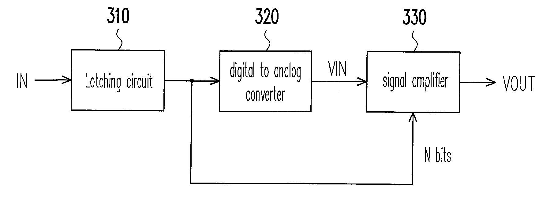
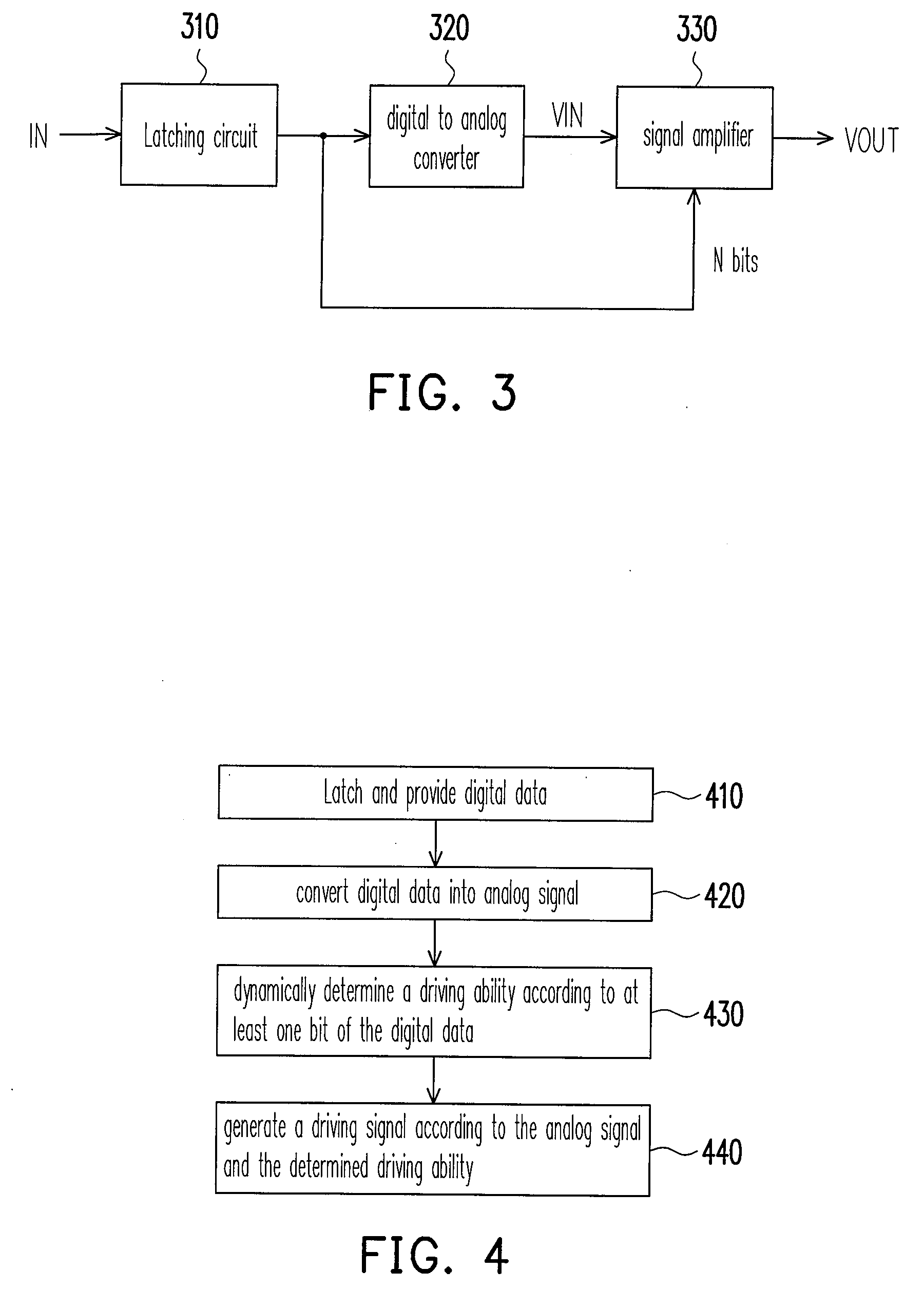
[0056]FIG. 3 is a block diagram of a driving apparatus according to an embodiment of the present invention. FIG. 4 is flow diagram showing a method of generating a driving signal according to an embodiment of the present invention. Refer to FIGS. 3 and 4 according to the requirements in the description. The driving apparatus in FIG. 3 includes a latching circuit 310, a digital to analog converter 320 and a signal amplifier 330. The latching cir...


PUM


Abstract

A driving apparatus and a driving method thereof are provided. The driving apparatus includes a digital to analog converter and a signal amplifier. The digital to analog converter is used for receiving a digital data and converting the digital data to an analog signal. The signal amplifier is coupled to the digital to analog converter. The signal amplifier is used for receiving the analog signal to generate a driving signal. The signal amplifier also dynamically changes the driving ability of the driving signal according to at least one bit of the digital data.

Description

CROSS-REFERENCE TO RELATED APPLICATION[0001]This application claims the priority benefit of Taiwan application serial no. 95150009, filed Dec. 29, 2006. All disclosure of the Taiwan application is incorporated herein by reference.BACKGROUND OF THE INVENTION[0002]1. Field of the Invention[0003]The present invention relates to a driving apparatus and a method of generating a driving signal, and more particularly to a driving apparatus and a method of generating a driving signal capable of reducing power consumption.[0004]2. Description of Related Art[0005]One of the characteristics of liquid crystal molecules is that they cannot remain unchanged under a certain fixed voltage. Otherwise, as time goes on, even if no voltage is applied, the liquid crystal molecules may not be able to rotate in response to an electric field variation as a result of characteristic disruption of the liquid crystal molecules so that different gray scales are formed. Therefore, driving the liquid crystal mole...

Claims


Application Information

Patent Timeline
IPC IPC(8): H03K3/00
CPCH03F3/45237H03F2200/411H03F2203/45514H03F2203/45504H03F2203/45466
Inventor HSU, MIN-CHIEHSUNG, KUANG-FENG
Owner NOVATEK MICROELECTRONICS CORP
Why Eureka
Try Eureka