
Method for operating a diesel engine in a homogeneous charge compression ignition combustion mode under idle and light-load operating conditions

Inactive Publication Date: 2008-07-03
SOUTHWEST RES INST
View PDF14 Cites 19 Cited by
  • Summary
  • Abstract
  • Description
  • Claims
  • Application Information

AI Technical Summary

Benefits of technology

[0010]Other features of the method for operating a diesel engine in an homogenous charge compression ignition combustion mode under idle and light load operating conditions, in accordance with the present invention, includes injecting fuel at a spray angle that is less than an angle at which fuel is injected for conventional diesel combustion and greater than an angle at which fuel impingement on the combustion chamber wall is avoided when the piston is positioned at 45° BTDC.
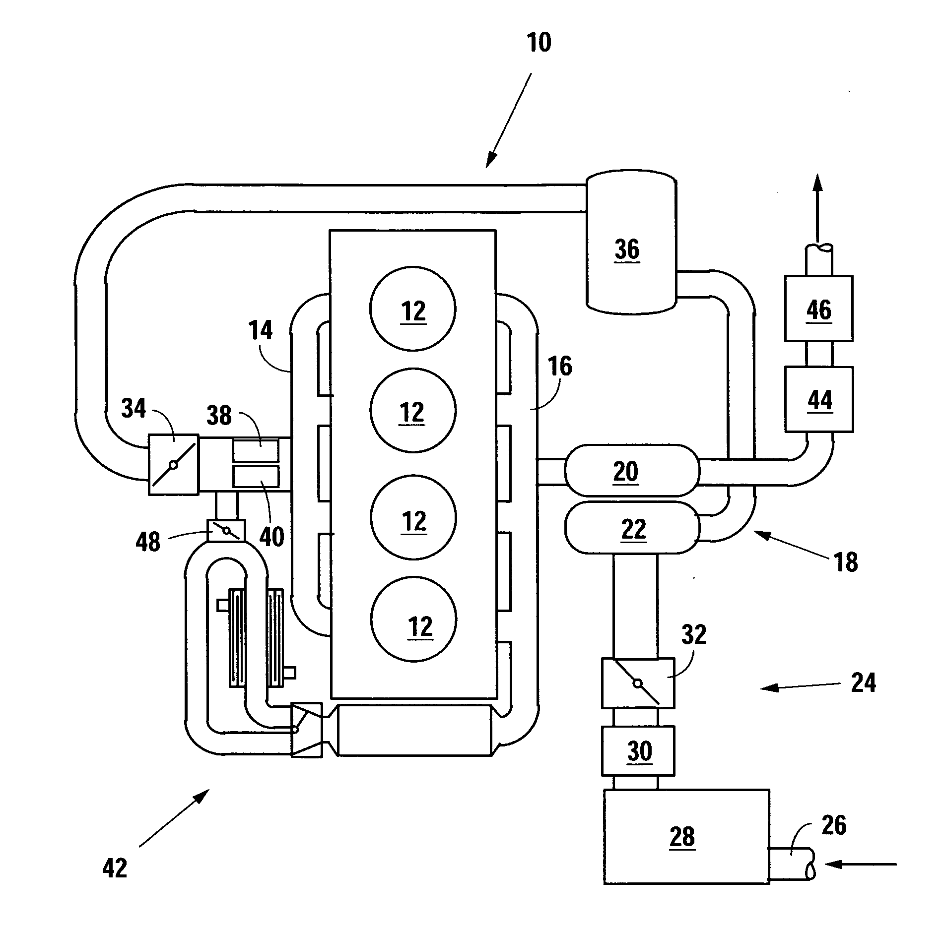
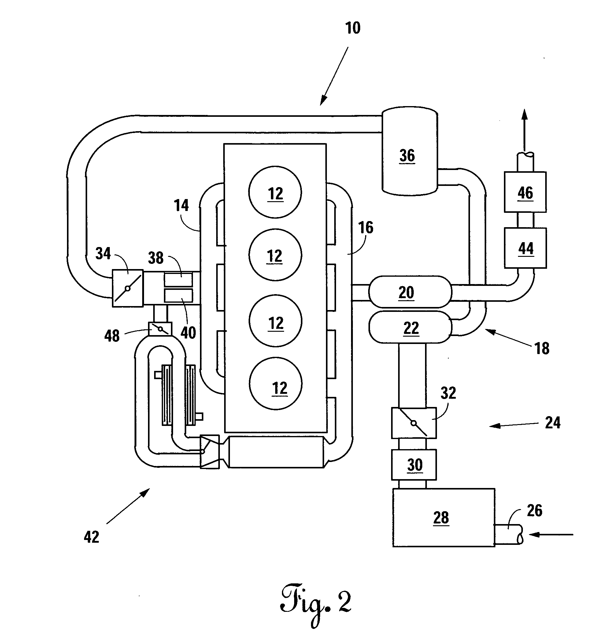
[0011]Other features of the method for operating a diesel engine, in accordance with the present invention, include at least partially closing an intake throttle valve to restrict the flow of intake air.

Problems solved by technology

However, exhaust gas treatment devices in general, and lean NOx traps and diesel particulate filters in particular, are not effective unless they are heated to a predefined operating, or activation, temperature.
During idle and low load operation, the exhaust gas temperature provided during conventional diesel combustion mode operation is often insufficient to maintain downstream exhaust gas after-treatment devices at their required operating temperature.
However, this specific multi-mode fuel injector does not provide sufficient dispersion of the fuel within the combustion chamber, a condition desirable for conventional diesel combustion mode operation.
However, the Schyu et al. injector tip is only applicable to narrow spray angle fuel injection useful in the very early injection of fuel and does not provide sufficient dispersion of the fuel for conventional diesel operation The present invention is specifically directed to overcoming the above-described problem associated with exhaust gas temperatures that are too low to maintain downstream exhaust gas aftertreatment devices at their respective required operating temperatures during idle and part load operation in a conventional diesel combustion mode and prevent liquid fuel impingement on the combustion chamber surfaces during HCCI combustion mode operation.

Method used


Image

  • Method for operating a diesel engine in a homogeneous charge compression ignition combustion mode under idle and light-load operating conditions
  • Method for operating a diesel engine in a homogeneous charge compression ignition combustion mode under idle and light-load operating conditions
  • Method for operating a diesel engine in a homogeneous charge compression ignition combustion mode under idle and light-load operating conditions

Examples


Embodiment Construction

[0017]Several methods have been used heretofore to form a homogenous fuel / air mixture with low volatility fuel, such as diesel fuel. For example, high temperature exhaust gas recirculation or heating of the intake air charge have been proposed to promote evaporation of the low volatility fuel. Also, multiple injections having a narrow spray angle of about 60° or less, beginning during the intake stroke or early in the compression stroke, have been proposed for use in HCCI combustion operations to increase fuel penetration distance and minimize the amount of liquid fuel deposited on combustion chamber surfaces.

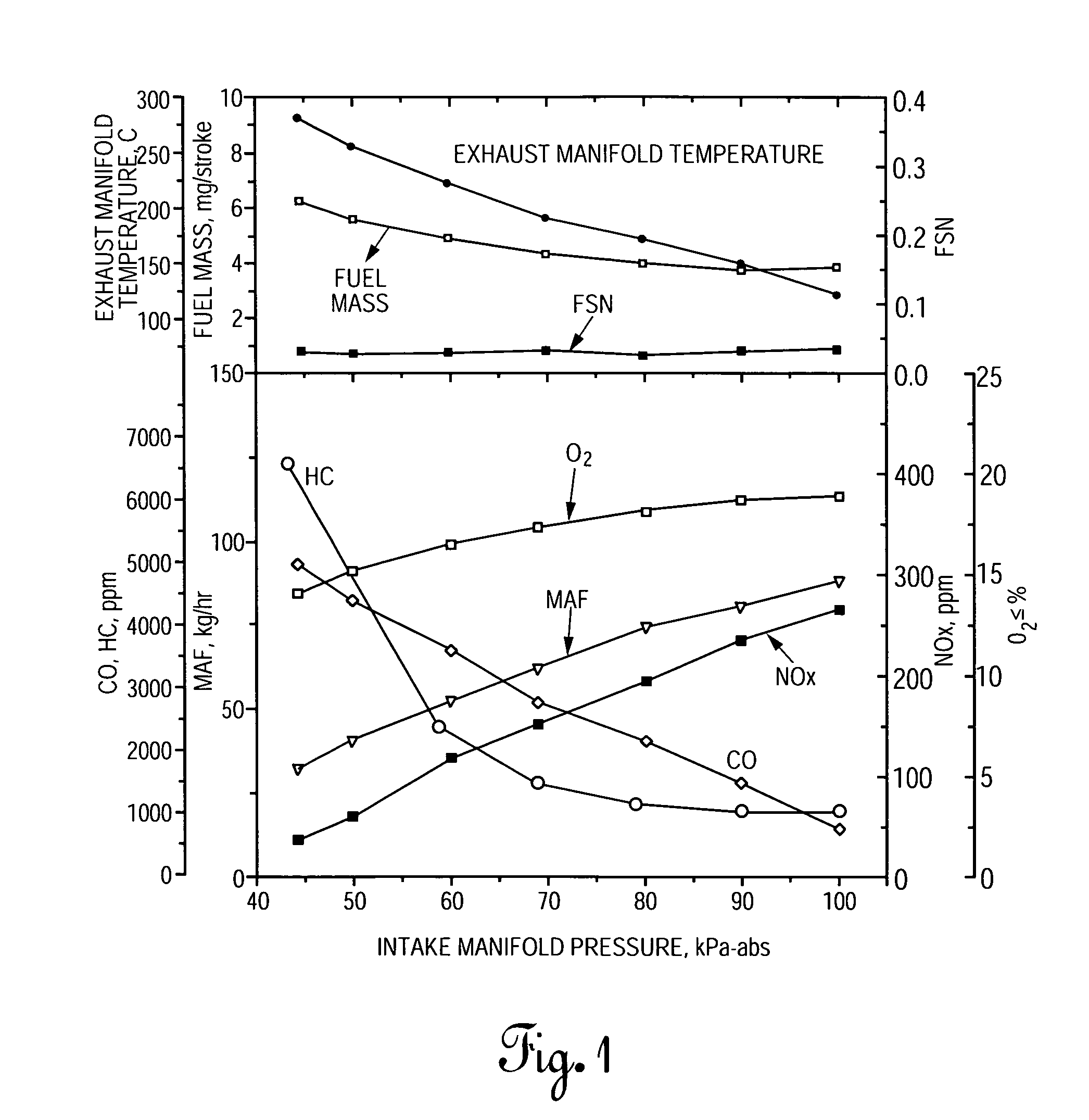
[0018]In a preferred embodiment of the present invention, throttling of the intake air is used to provide an intake manifold pressure that is below the pressure of the ambient atmosphere, i.e., less than 100 kPa-absolute. The term “intake manifold pressure” as used herein and in the claims, means the pressure of the intake air charge at the intake ports of the combustion chambe...


PUM


Abstract

Intake air is restricted to provide an intake manifold pressure that is below the pressure of the ambient atmosphere. Fuel is injected into each combustion chamber at a position of between 15° and 45° BTDC to achieve HCCI combustion under idle and light load operating conditions.

Description

BACKGROUND OF THE INVENTION[0001]1. Technical Field[0002]This invention relates generally to a method for operating a diesel engine, and more particularly to such a method for operating a diesel engine under idle and light-load operating conditions.[0003]2. Background Art[0004]Conventional diesel combustion produces relatively high concentrations of various oxides of nitrogen (NOx) and particulate matter (PM), because the diffusion flame, i.e., a long gas flame that radiates uniformly over its length and precipitates free-carbon uniformly, results in fuel droplets dispersed in the fuel / air (F / A) charge burning stoichiometrically. The U.S. Environmental Protection Agencies (EPA) has set very stringent emissions standards for diesel engines. Exhaust gas treatment devices have been, and are currently being, developed to reduce undesirable emissions from diesel engines. At the present time, lean NOx traps (LNTs) are the most likely exhaust treatment devices for the control of NOx emissi...

Claims


Application Information

Patent Timeline
IPC IPC(8): F02B3/06
CPCF02B1/12F02B23/0669F02B23/0672F02D41/0002F02D41/08Y02T10/42F02D2041/0022F02M25/0707F02M25/0728Y02T10/128Y02T10/44F02D41/401F02M26/05F02M26/25Y02T10/12Y02T10/40
Inventor HUANG, YIQUN
Owner SOUTHWEST RES INST
Learn More