
Near-field vector signal enhancement

a vector signal and enhancement technology, applied in the direction of transducer casings/cabinets/supports, loudspeakers, electrical transducers, etc., can solve the problems of changing the purity of the remaining voice signal, affecting the performance of the voice signal, and contaminating the voice signal, so as to achieve the effect of better demonstrating the improvement of performan

Inactive Publication Date: 2008-06-26
DOLBY LAB LICENSING CORP
View PDF12 Cites 57 Cited by
  • Summary
  • Abstract
  • Description
  • Claims
  • Application Information

AI Technical Summary

Benefits of technology

[0015]In accordance with one embodiment described herein, there is provided a voice sensing method for significantly improved voice pickup in noise applicable for example in a wireless headset. Advantageously it provides a clean, non-distorted voice signal with excellent noise removal, wherein small residual noise is not distorted and retains its original character. Functionally, a voice pickup method for better selecting the user's voice signal while rejecting noise signals is provided.
[0017]Benefits of the system disclosed herein include an attenuation of far-field noise signals at a rate twice that of prior art systems while maintaining flat frequency response characteristics. They provide clean, natural voice output, highly reduced noise, high compatibility with conventional transmission channel signal processing technology, natural sounding low residual noise, excellent performance in extreme noise conditions—even in negative SNR conditions—instantaneous response (no adaptation time problems), and yet demonstrate low compute power, memory and hardware requirements for low cost applications.
[0019]The system described herein can be used to accurately sense local noises, so that these local noise signals can be removed from mixed signals that contain desired far-field signals, thereby obtaining clean sensing of the far-field signals.
[0021]The system does not change the purity of the remaining voice while improving upon the signal-to-noise-ratio (SNR) improvement performance of beamforming-based systems and it adapts much more quickly than do GSC or BSS methods. With these other systems, SNR improvements are still below 10-dB in most high noise applications.

Problems solved by technology

When communicating in noisy ambient conditions, a voice signal may be contaminated by the simultaneous pickup of ambient noises.
However, when the “noise” consists of other voices or voice-like signals, single-channel methods fail.
Further, as the amount of noise removal is increased, some of the voice signal is also removed, thereby changing the purity of the remaining voice signal—that is, the voice becomes distorted.
Further, the residual noise in the output signal becomes more voice-like.
When used with speech recognition software, these defects decrease recognition accuracy.
These systems are limited in their ability to improve signal-to-noise ratio (SNR), usually by the practical number of sensors that can be employed.
Further, null steering (Generalized Sidelobe Canceller or GSC) and separation (Blind Source Separation or BSS) methods require time to adapt their filter coefficients, thereby allowing significant noise to remain in the output during the adaptation period (which can be many seconds).
Thus, GSC and BSS methods are limited to semi-stationary situations.
However, demand has driven a reduction in the size of headset devices so that a conventional prior art boom microphone solution has become unacceptable.
However, noise signals, which are generally arriving from distant locations, are not reduced so the result is a degraded signal-to-noise ratio (SNR).
These methods introduce additional problems: the proximity effect, exacerbated wind noise sensitivity and electronic noise, frequency response coloration of far-field (noise) signals, the need for equalization filters, and if implemented electronically with dual microphones, the requirement for microphone matching.
In practice, these systems also suffer from on-axis noise sensitivity that is identical to that of their omni-directional brethren.
In order to achieve better performance, second-order directional systems (e.g. U.S. Pat. No. 5,473,684 by Bartlett and Zuniga entitled “Noise-canceling Differential Microphone Assembly”) have also been attempted, but the defects common to first-order systems are also greatly magnified so that wind noise sensitivity, signal coloration, electronic noise, in addition to equalization and matching requirements, make this approach unacceptable.
Such systems suffer from increased complexity and cost, multiple sensors requiring matching, slow response to moving or rapidly changing noise sources, incomplete noise removal and voice signal distortion and degradation.
Another drawback is that these systems operate only with relatively clean (positive SNR) input signals, and actually degrade the signal quality when operating with poor (negative SNR) input signals.
The voice degradation often interferes with Automatic Speech Recognition (ASR), a major application for such headsets.
The downsides are that this technology significantly distorts the desired target signal and requires excellent microphone array element matching.
Unfortunately, when there is more than a single noise source at a particular frequency, this system can not optimally reduce the noise.
In real situations, even if there is only one physical noise source, room reverberations effectively create additional virtual noise sources with many different directions of arrival, but all having the identical frequency content thereby circumventing this method's ability to operate effectively.
In addition, by being adaptive, this scheme requires substantial time to adjust in order to minimize the noise in the output signal.
Further, the rate of noise attenuation vs. distance is limited and the residual noise in the output signal is highly colored, among other defects.

Method used


Image

  • Near-field vector signal enhancement
  • Near-field vector signal enhancement
  • Near-field vector signal enhancement

Examples


Embodiment Construction

[0040]Embodiments of the present invention are described herein in the context of near-field pick-up systems. Those of ordinary skill in the art will realize that the following detailed description of the present invention is illustrative only and is not intended to be in any way limiting. Other embodiments of the present invention will readily suggest themselves to such skilled persons having the benefit of this disclosure. Reference will now be made in detail to implementations of the present invention as illustrated in the accompanying drawings. The same reference indicators will be used throughout the drawings and the following detailed description to refer to the same or like parts.

[0041]In the interest of clarity, not all of the routine features of the implementations described herein are shown and described. It will, of course, be appreciated that in the development of any such actual implementation, numerous implementation-specific decisions must be made in order to achieve ...


PUM


Abstract

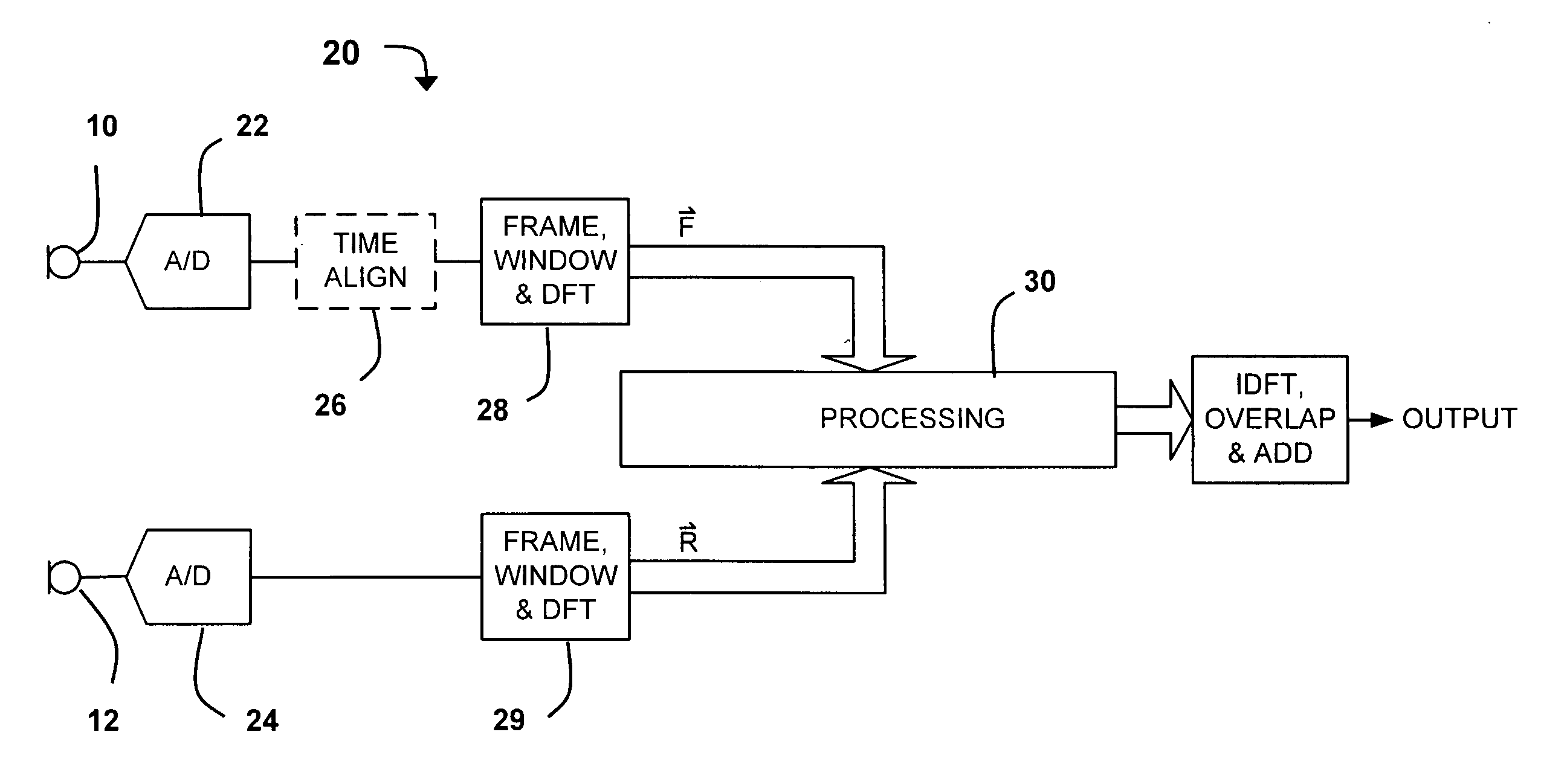
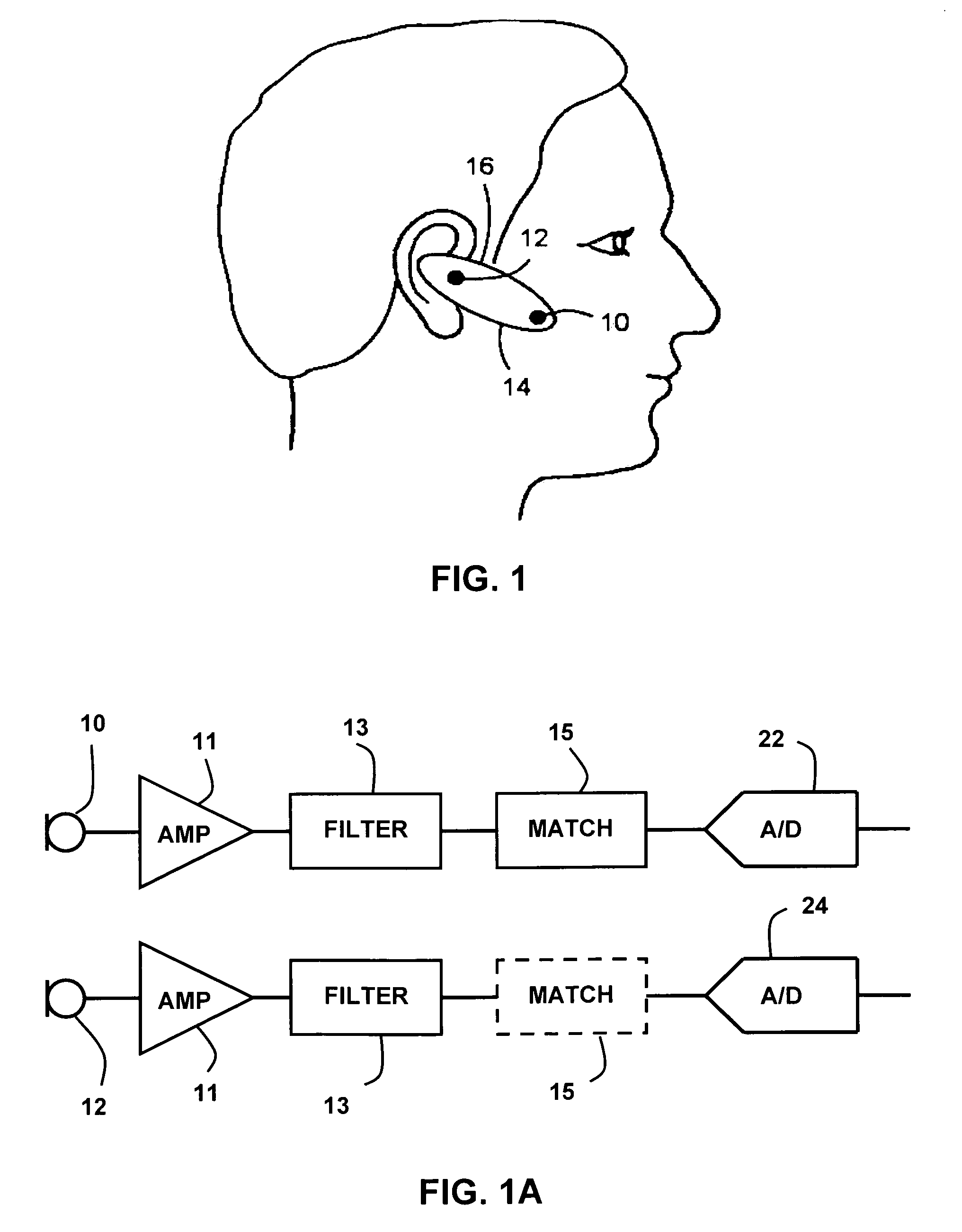
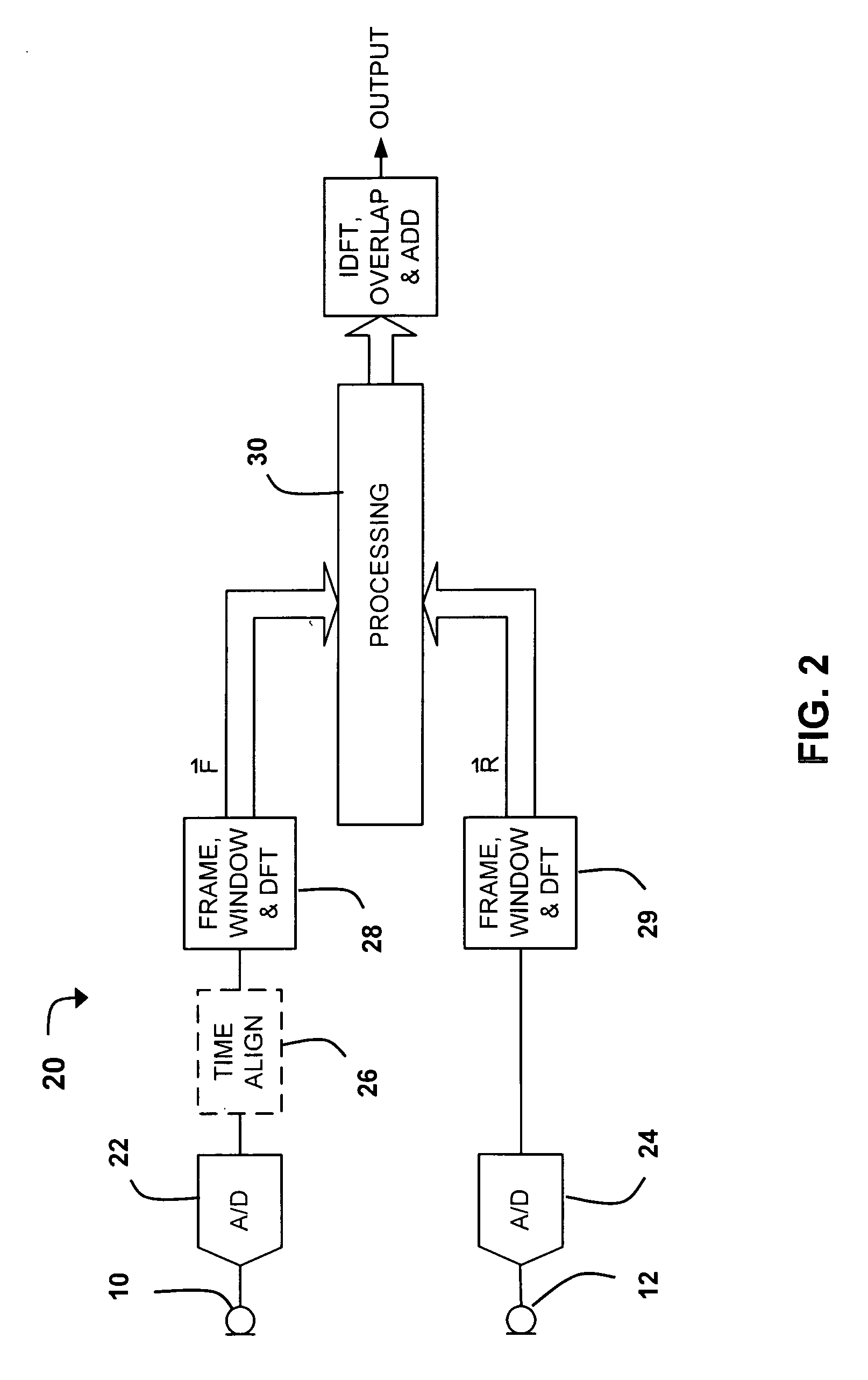
Near-field sensing of wave signals, for example for application in headsets and earsets, is accomplished by placing two or more spaced-apart microphones along a line generally between the headset and the user's mouth. The signals produced at the output of the microphones will disagree in amplitude and time delay for the desired signal—the wearer's voice—but will disagree in a different manner for the ambient noises. Utilization of this difference enables recognizing, and subsequently ignoring, the noise portion of the signals and passing a clean voice signal. A first approach involves a complex vector difference equation applied in the frequency domain that creates a noise-reduced result. A second approach creates an attenuation value that is proportional to the complex vector difference, and applies this attenuation value to the original signal in order to effect a reduction of the noise. The two approaches can be applied separately or combined.

Description

CROSS-REFERENCE TO RELATED APPLICATIONS[0001](Not Applicable)BACKGROUND OF THE INVENTION[0002]1. Field of the Invention[0003]The invention relates to near-field sensing systems.[0004]2. Description of the Related Art[0005]When communicating in noisy ambient conditions, a voice signal may be contaminated by the simultaneous pickup of ambient noises. Single-channel noise reduction methods are able to provide a measure of noise removal by using a-priori knowledge about the differences between voice-like signals and noise signals to separate and reduce the noise. However, when the “noise” consists of other voices or voice-like signals, single-channel methods fail. Further, as the amount of noise removal is increased, some of the voice signal is also removed, thereby changing the purity of the remaining voice signal—that is, the voice becomes distorted. Further, the residual noise in the output signal becomes more voice-like. When used with speech recognition software, these defects decr...

Claims


Application Information

Patent Timeline
IPC IPC(8): H04B15/00
CPCH04R1/1091H04R3/005H04R25/405H04R2410/07H04R2201/403H04R2410/05H04R25/407
Inventor TAENZER, JON C.
Owner DOLBY LAB LICENSING CORP
Learn More