Non-Circular Wire Crop Pick-Up Tooth

a crop pick-up tooth and non-circular wire technology, applied in the field of crop pick-up machinery, can solve the problems of undue stress on the tine coil, failure of yielding and fatigue, and relatively short load cycle, so as to improve dampening, reduce stress, and improve feeding.

Inactive Publication Date: 2008-06-19
DEERE & CO
View PDF11 Cites 3 Cited by
  • Summary
  • Abstract
  • Description
  • Claims
  • Application Information

AI Technical Summary

Benefits of technology

The present invention provides an improved spring tooth for a crop pick-up machine. The spring tooth is made of wire with a square, hexagonal, or parallelogram cross-section and has rounded corners to reduce stress concentrations and force the maximum stresses away from the inner and outer diameters of the spring coil of the teeth. The dampening characteristic of the teeth can be increased by providing a rubber mounting for the teeth. The technical effects of the invention are improved feeding, reduced stress, and improved dampening.

Problems solved by technology

Teeth used on crop pick-up machinery have been considered a common replacement item on such machinery due to yielding and breakage since their conception due to being subject to rough ground and tough crop conditions.
Stiff or ultra-stiff pick-up teeth (see U.S. Pat. No. 5,394,682), which are measurably stiffer than previous tooth designs to aid in positive crop feeding, experience relatively high stress levels leading to yielding and fatigue failures—during field operation.
When mounted to tooth bars constructed as channel members (see U.S. Pat. No. 6,327,840, for example), the spring coil joined to the tines tends to rotate, when the tine is under load, about an instant center located at the line contact between the outer first coil of the spring coil and the channel leg opposite the tine under load such that the load between the first coil and the leg is concentrated, resulting in undue stress on the tine coil and breakage after only a relatively short number of load cycles.
Thus, the problem to be solved is to maintain the use of stiff or ultra-stiff teeth for superior crop feeding performance, but to lower the stresses experienced by the teeth so as to result in a substantially longer tooth life.

Method used


Image

  • Non-Circular Wire Crop Pick-Up Tooth
  • Non-Circular Wire Crop Pick-Up Tooth
  • Non-Circular Wire Crop Pick-Up Tooth

Examples


Embodiment Construction

[0014]Preliminarily, it is to be noted that various components are described as existing in pairs while only one of each pair is illustrated, with it to be understood that the unshown component is the same as, or a mirror image of, the illustrated component.

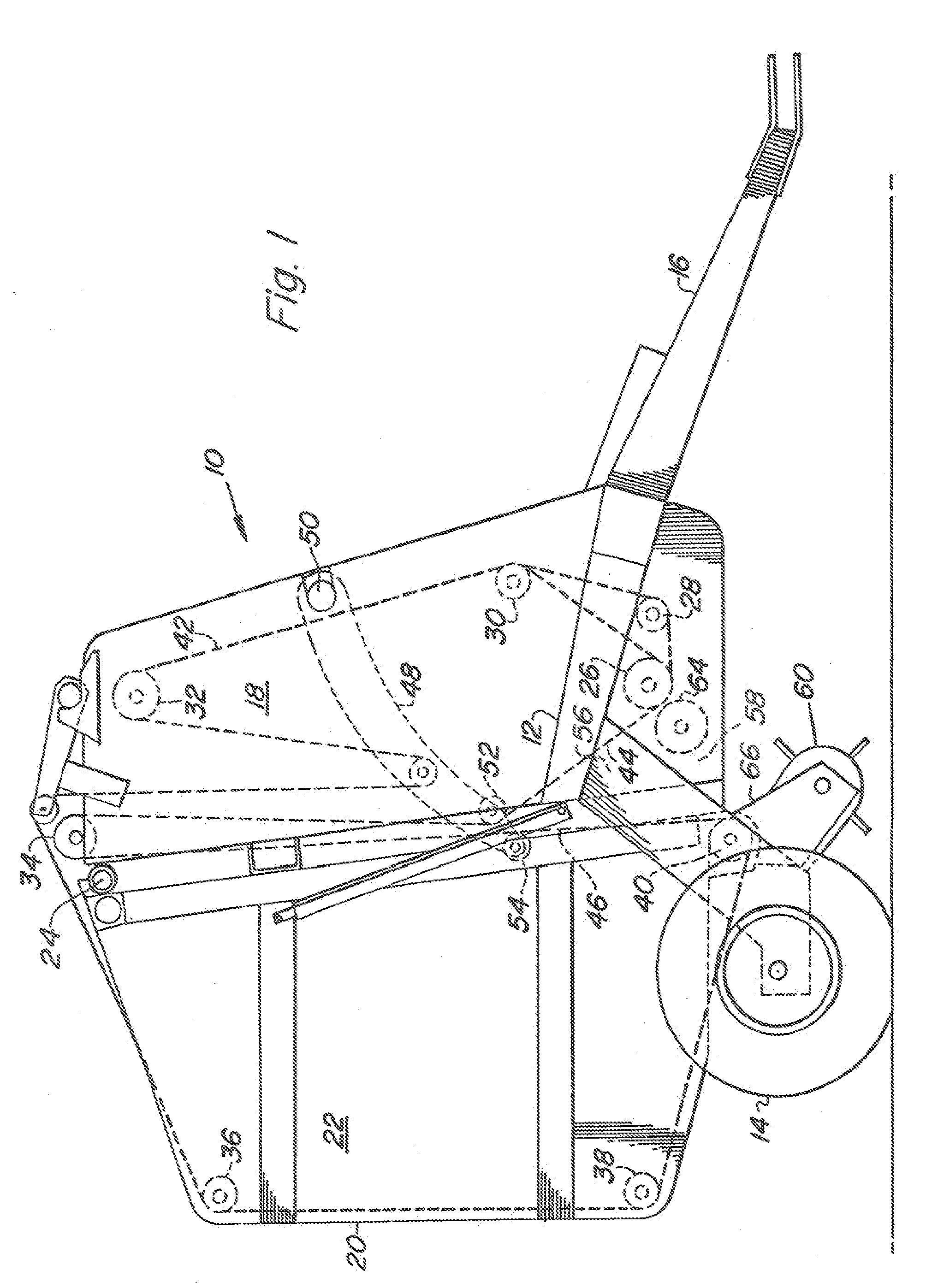
[0015]Referring now to FIG. 1, there is shown a baler 10 of the type for making large cylindrical bales and commonly called a large round baler. The baler 10 comprises a main frame 12 supported on a pair of ground wheels 14 and having a draft tongue 16 secured thereto and adapted for being connected to a towing vehicle, such as an agricultural tractor. A pair of transversely spaced vertical sidewalls 18 is joined to the frame 12, with the sidewalls 18 having respective upright rear edges. A bale discharge gate 20 including opposite side walls 22 is vertically pivotally attached, as at 24, to upper rear locations of the sidewalls 18. The sidewalls 22 have forward upright edges which abut against the rearward edges of the sidewalls...


PUM


Abstract

Spring teeth for a harvesting machine are each constructed of spring wire having a square cross section and being wound so as to define a coil torsion spring section terminating in a tine, with the tine having a leading flat surface, considered relative to the engagement of tine with the crop during pick-up operation, and having a trailing flat surface disposed parallel to said leading flat surface. The coil torsion spring is mounted to a tooth bar formed as a channel member such that the outer surface of the coils make a relatively large area contact with the tooth bar at location spaced approximately 180° from where the tine joins the coil torsion spring. This together with the fact that the contact area of the flat sides of the wire in the coil region is also quite large leads to a damping action that lessens stress in the tooth assembly.

Description

FIELD OF THE INVENTION[0001]The present invention relates to crop pick-up machinery, and, more specifically relates to pick-up spring teeth.BACKGROUND OF THE INVENTION[0002]Teeth used on crop pick-up machinery have been considered a common replacement item on such machinery due to yielding and breakage since their conception due to being subject to rough ground and tough crop conditions. Although replacing teeth has become a routine service activity, any means to minimize the amount of replacement is valued by customers. Pick-up teeth are designed to flex out of the way of obstacles and relieve overload stresses. Two common pick-up tooth designs are coil torsion spring teeth or rubber-mounted tines, both using round wire. Both of these designs rely on dampening to prevent yield and fatigue due to rebound, with the torsion spring teeth using inter-coil and coil-to-mounting surface friction to produce dampening, while the rubber mounted teeth use the dampening nature of the rubber to ...

Claims


Application Information

Patent Timeline
Patent Type & Authority Applications(United States)
IPC IPC(8): A01D78/00
CPCA01D89/002A01D80/02
Inventor DERSCHEID, DANIEL ERICANSTEY, HENRY DENNIS
Owner DEERE & CO
Why Eureka
Try Eureka