
Spinal stabilization system and method

a stabilization system and spine technology, applied in the field of medical devices, can solve the problems of pain and/or partial or complete loss of mobility, interbody devices alone may not be able to support a portion of the spine sufficiently, and the insertion of the pedicle screw may require highly invasive surgery, so as to promote bone growth, promote bone growth, and restore the stability of the lumbosacral region of the spin

Active Publication Date: 2008-06-12
ZIMMER BIOMET SPINE INC
View PDF11 Cites 94 Cited by
  • Summary
  • Abstract
  • Description
  • Claims
  • Application Information

AI Technical Summary

Benefits of technology

[0012]A spinal stabilization system may be used to increase stability of a portion of a spine. The spinal stabilization system may require a minimally intrusive surgical installation procedure. The spinal stabilization system may provide flexion / extension, torsion, and lateral bending stability to at least a portion of a spine. The system may be used as a stand-alone system or used in combination with other systems or devices.
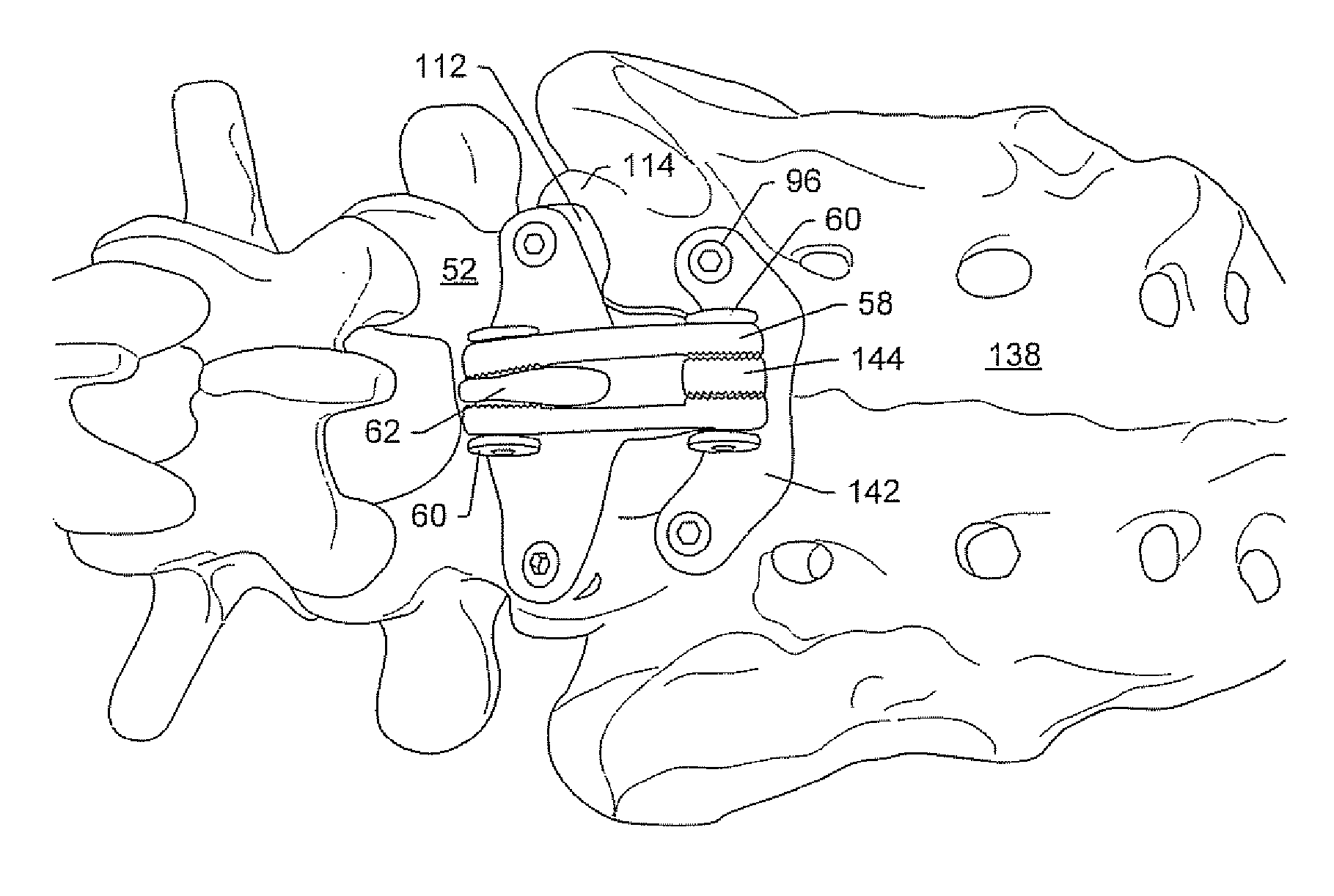
[0018]A spinal stabilization system may be adapted to stabilize a portion of a spine where a spinous process is not present, has been damaged or removed, or is not capable of withstanding structural loads for spinal fixation. For example, a spinal stabilization system may provide or restore stability to the lumbosacral region of the spine. An artificial spinous process may be inserted to function as a spinous process for the stabilization system.
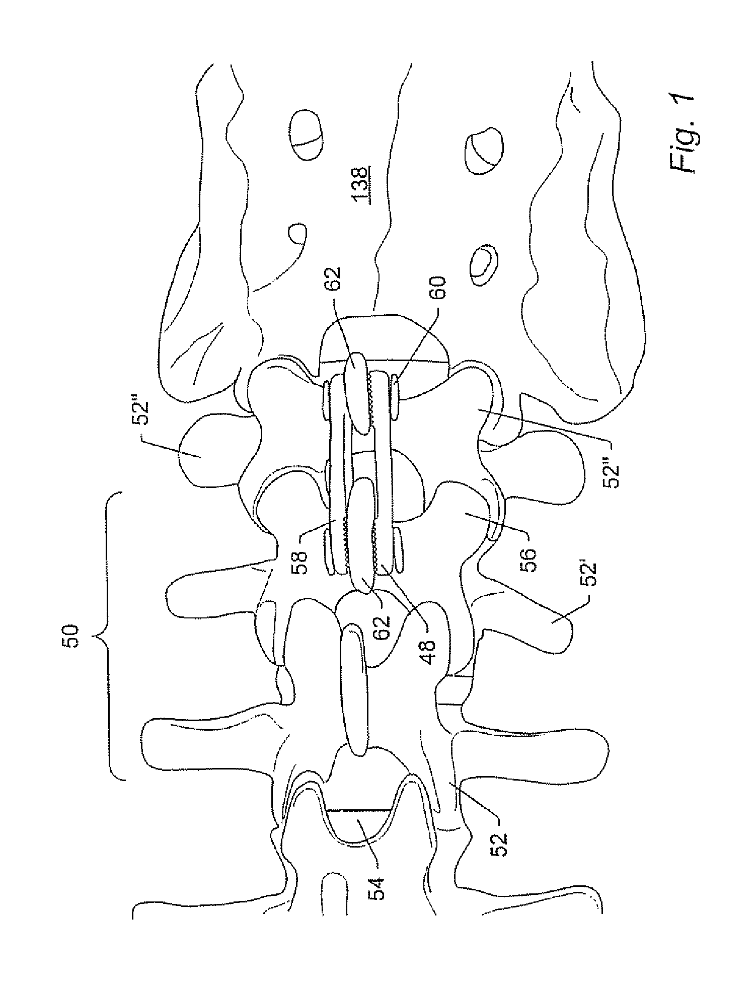
[0019]Spinal stabilization systems may stabilize more than one vertebral level. For example, a spinal stabilization system may couple a first vertebra to an adjacent second vertebra (one vertebral level). The second vertebra may be coupled to an adjacent third vertebra. The spatial and angular relationship between the first and second vertebrae and the second and third vertebrae may be different. A spinal stabilization system may maintain the natural spatial and angular relationship between the adjacent vertebral levels. In some embodiments, the spinal stabilization system may establish a desired spatial and angular relationship between adjacent vertebrae.
[0020]Fusion between vertebrae may be desirable for stabilization and permanent fixation of a portion of a spine. A spinal stabilization system may accommodate means for promoting bone growth between adjacent vertebrae. Bone graft may be placed adjacent to a structural member of a spinal stabilization system and the spinous processes of adjacent vertebrae coupled to the structural member to promote fusion between the vertebrae. Additionally, bone graft may be placed between an articular facet joint of adjacent vertebrae after removing the necessary soft tissue or exposing the inter-articular space. A fastener may be positioned through portions of the adjacent vertebrae and the facet joint to immobilize the joint and promote bone growth, A spinal fixation system may be used to substantially increase the stability of a portion of a spine containing an interbody fusion device and also relieve a significant amount of pressure on the interbody device.

Problems solved by technology

In some instances, the effects of spinal instability may result in pain and / or partial or complete loss of mobility.
In some instances, interbody devices alone may not be capable of supporting a portion of a spine sufficiently to promote vertebral fusion.
In addition, pedicle screw insertion may require highly invasive surgery.
Such surgery may result in extended recovery times or even irreparable damage to adjacent tissues.

Method used


Image

  • Spinal stabilization system and method
  • Spinal stabilization system and method
  • Spinal stabilization system and method

Examples


Embodiment Construction

[0050]A spinal stabilization system may provide stabilization for one or more vertebral levels of a spine. In some embodiments, a spinal stabilization system may be utilized as a stand-alone system. In some embodiments, a spinal stabilization system may be used in conjunction with other systems or devices to provide stability to the spine. For example, a spinal stabilization system may be used in conjunction with a spinal implant (e.g., an interbody fusion device, an artificial disc, and / or a vertebral construct). The spinal stabilization system may be easy to install with only minimal intrusion to adjacent tissue and muscle as compared to conventional stabilization systems. In addition, the spinal stabilization system may provide minimal risk of dural or neural damage during installation and use.

[0051]Appropriately sized spinal stabilization systems may be used to couple adjacent vertebrae of a spinal column. For example, an appropriately sized spinal stabilization system may be us...


PUM


Abstract

A spinal stabilization system may include a pair of structural members coupled to at least a portion of a human vertebra with connectors. Connectors may couple structural members to spinous processes. Some embodiments of a spinal stabilization system may include fasteners that couple structural members to vertebrae. In some embodiments, a spinal stabilization system provides three points of fixation for a single vertebral level. A fastener may fixate a facet joint between adjacent vertebrae and couple a stabilization structural member to a vertebra. Connectors may couple the structural members to the spinous processes of the vertebrae. Use of a spinal stabilization system may improve the stability of a weakened or damaged portion of a spine. When used in conjunction with an implant or other device, the spinal stabilization system may immobilize vertebrae and allow for fusion of the implant or other device with vertebrae.

Description

PRIORITY CLAIM[0001]This application claims priority to U.S. Provisional Application No. 60 / 306,765 entitled “Spinal Stabilization System and Method,” filed Jul. 20, 2001. The above-referenced provisional application is incorporated by reference as if fully set forth herein.BACKGROUND OF THE INVENTION[0002]1. Field of the Invention[0003]The present invention generally relates to the field of medical devices, and more particularly to a system for stabilizing a portion of a spinal column. In an embodiment, the system joins together adjacent spinous processes to stabilize a portion of a spine.[0004]2. Description of Related Art[0005]Spinal instability may result from many factors including trauma or degenerative disorders stemming from injuries and / or aging. In some instances, the effects of spinal instability may result in pain and / or partial or complete loss of mobility.[0006]Several devices and techniques have been developed to restore stability to the spine. For example, interbody ...

Claims


Application Information

Patent Timeline
Patent Type & Authority Applications(United States)
IPC IPC(8): A61B17/70A61B17/88A61B17/58A61F2/44
CPCA61B17/1604A61B17/1606A61B17/7068A61B17/7067A61B17/1671A61B2017/564
Inventor MITCHELL, MARGARET E.LANDRY, MICHAEL E.HOCHSCHULER, STEPHEN H.GUYER, RICHARD D.
Owner ZIMMER BIOMET SPINE INC
Learn More