Audio reproducing apparatus

a technology of reproducing apparatus and audio, which is applied in the direction of frequency response correction, electrical transducers, instruments, etc., can solve the problem of insufficient low frequency sound effect, and achieve the effect of reducing the degree of distortion in the sound

Inactive Publication Date: 2008-06-05
SONY CORP
View PDF6 Cites 7 Cited by
  • Summary
  • Abstract
  • Description
  • Claims
  • Application Information

AI Technical Summary

Benefits of technology

[0019]In accordance with the embodiment of the present invention, if a low-frequency component of the audio signal is lower in frequency than the resonance frequency f0, the sound of the harmonic overtone component obtained from the low-frequency component is emitted from a loudspeaker. When the harmonic overtone component is output, the level thereof is dynamically changed. A crisp low-frequency sound effect is thus provided while the degree of distortion in the sound is reduced.

Problems solved by technology

If the harmonic overtone component S8 is reduced in amount to lower the degree of distortion, the low frequency sound effect becomes insufficient.

Method used


Image

  • Audio reproducing apparatus
  • Audio reproducing apparatus
  • Audio reproducing apparatus

Examples


Embodiment Construction

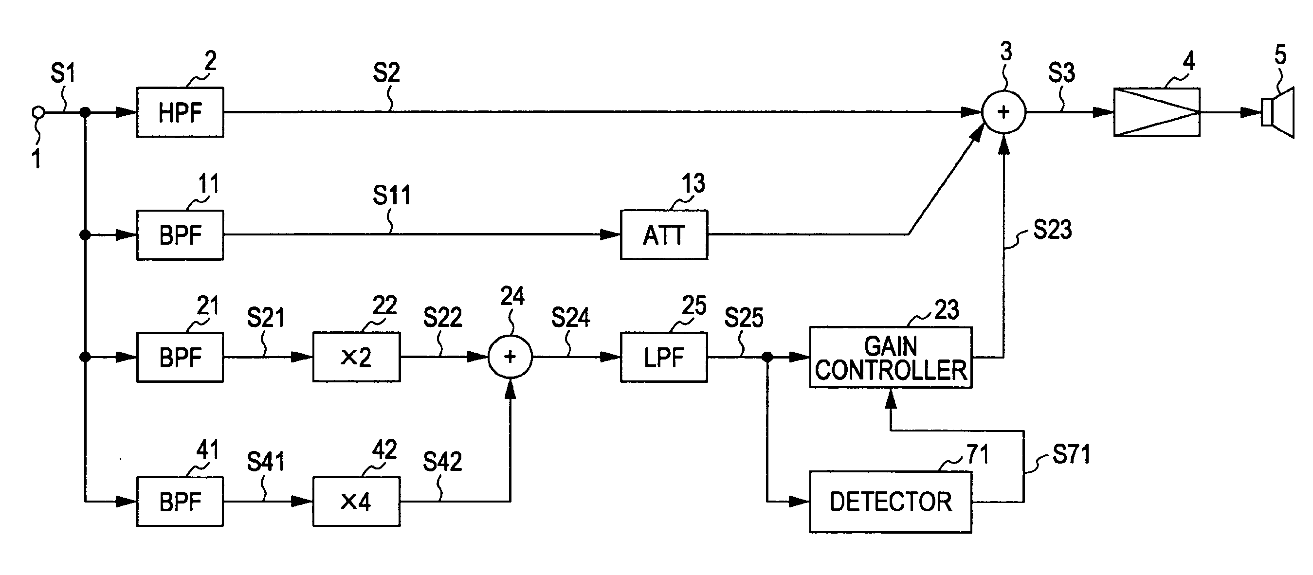
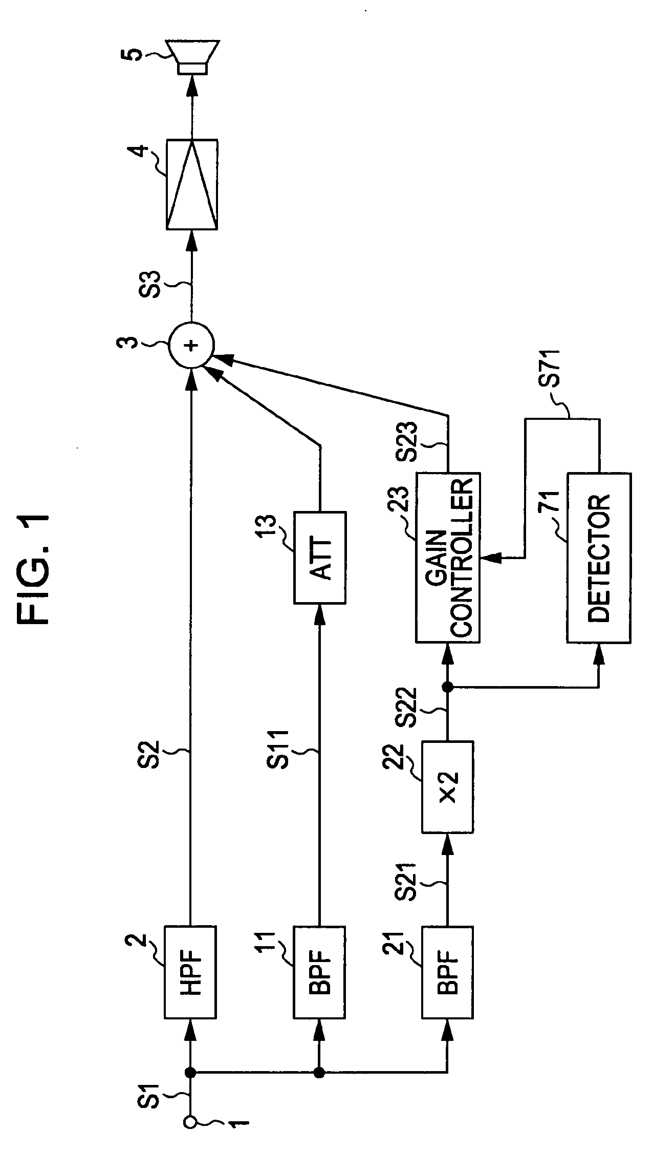
[0034]FIG. 1 illustrates an audio signal processing apparatus in accordance with one embodiment of the present invention. A small loudspeaker 5 provides an improved low frequency sound effect. Let f0 represent a resonance frequency of the loudspeaker 5. The resonance frequency f0 is 100 Hz or lower. Let f1 represent a frequency upper limit below which a signal obtained by frequency multiplying a fundamental frequency signal causes no unpleasant hearing impression. The frequency upper limit f1 is a frequency obtained by frequency multiplying a fundamental frequency of a signal. The frequency upper limit f1 is about 200 Hz. Here, f0=f1 / 2 (or f0≦f1 / 2). In the case of a two-channel stereophonic system or multi-channel stereophonic system, each channel has the structure of FIG. 1.

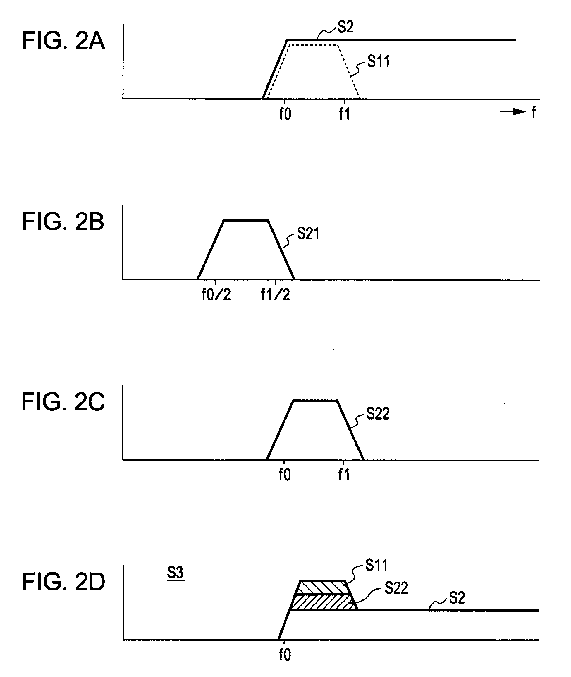
[0035]An audio signal S1 is supplied to a high-pass filter 2 via an input terminal 1. As represented by a solid line in FIG. 2A, a middle to high frequency component S2 equal to or higher than the resonance freq...


PUM


Abstract

An audio signal processing apparatus includes a high-pass filter for extracting from an audio signal a frequency component higher than f0, n band-pass filters for extracting, from the audio signal, frequency components falling within a frequency range from f0 / N to f1 / N, n harmonic overtone generators for frequency multiplying each of outputs of the n band-pass filters by N, a first combining unit for combining the generated harmonic overtone components, a level detector for detecting a level of a supplied harmonic overtone component, a gain controller for controlling dynamically the harmonic overtone component supplied from the first combining unit, and a second combining unit for combining the frequency component extracted by the high-pass filter and a harmonic overtone component output from the gain controller, where N is (n being a natural number), f0 is a first predetermined frequency, and f1 is a second predetermined frequency higher than f0.

Description

CROSS REFERENCES TO RELATED APPLICATIONS[0001]The present invention contains subject matter related to Japanese Patent Application JP 2006-283533 filed in the Japanese Patent Office on Oct. 18, 2006, the entire contents of which are incorporated herein by reference.BACKGROUND OF THE INVENTION[0002]1. Field of the Invention[0003]The present invention relates to an audio reproducing apparatus.[0004]2. Description of the Related Art[0005]Small loudspeakers are employed in minicomponent stereo sets and flat-screen television receivers. In such applications, the enclosure of the loudspeaker (speaker box) is accordingly small. The resonance frequency f0 of the loudspeaker is as high as or higher than 100 Hz.[0006]An audio signal having the resonance frequency f0 or lower may be supplied to the loudspeaker. With the frequency being lowered, the fundamental component is increasingly lowered while distorted components (harmonic components) sharply increases in the sound output pressure there...

Claims


Application Information

Patent Timeline
Patent Type & Authority Applications(United States)
IPC IPC(8): H03G9/00
CPCH03G5/165H04R2430/03H04R3/04
Inventor SHIMURA, MASARUNAKAGAMI, TAROOHKURI, KAZUNOBU
Owner SONY CORP
Why Eureka
Try Eureka