Electrical connection device

a technology of electrical connection and connection device, which is applied in the direction of connection, coupling device connection, electrical apparatus, etc., can solve the problems of severe signal distortion and unaddressed, and achieve the effects of reducing the degree of distortion of high-frequency signal transmission, enhancing signal transmission quality, and reducing the negative influence of electrical stub effect on signal transmission

Active Publication Date: 2018-10-25
LOTES
View PDF2 Cites 0 Cited by
  • Summary
  • Abstract
  • Description
  • Claims
  • Application Information

AI Technical Summary

Benefits of technology

The present invention provides a new electrical connection device that eliminates the negative influence of the "electrical stub effect" on signal transmission, improves the quality of signal transmission, and decreases the degree of distortion of high-frequency signal transmission. This is achieved by ensuring a tight contact between the two conductors, complete attachment to the top surface, and the absence of an open circuit caused by a branch between the two conductors.

Problems solved by technology

As a result, there is a electrical stub effect, which affects the quality of signal transmission, and in particular, in high-frequency signal transmission, the negative influence of the electrical stub effect is especially evident, causing severe signal distortion.
Therefore, a heretofore unaddressed need to design a new electrical connection device exists in the art to address the aforementioned deficiencies and inadequacies.

Method used


Image

  • Electrical connection device
  • Electrical connection device
  • Electrical connection device

Examples


Embodiment Construction

[0037]The present invention is more particularly described in the following examples that are intended as illustrative only since numerous modifications and variations therein will be apparent to those skilled in the art. Various embodiments of the invention are now described in detail. Referring to the drawings, like numbers indicate like components throughout the views. As used in the description herein and throughout the claims that follow, the meaning of “a”, “an”, and “the” includes plural reference unless the context clearly dictates otherwise. Also, as used in the description herein and throughout the claims that follow, the meaning of “in” includes “in” and “on” unless the context clearly dictates otherwise. Moreover, titles or subtitles may be used in the specification for the convenience of a reader, which shall have no influence on the scope of the present invention.

[0038]It will be understood that when an element is referred to as being “on” another element, it can be di...


PUM


Abstract

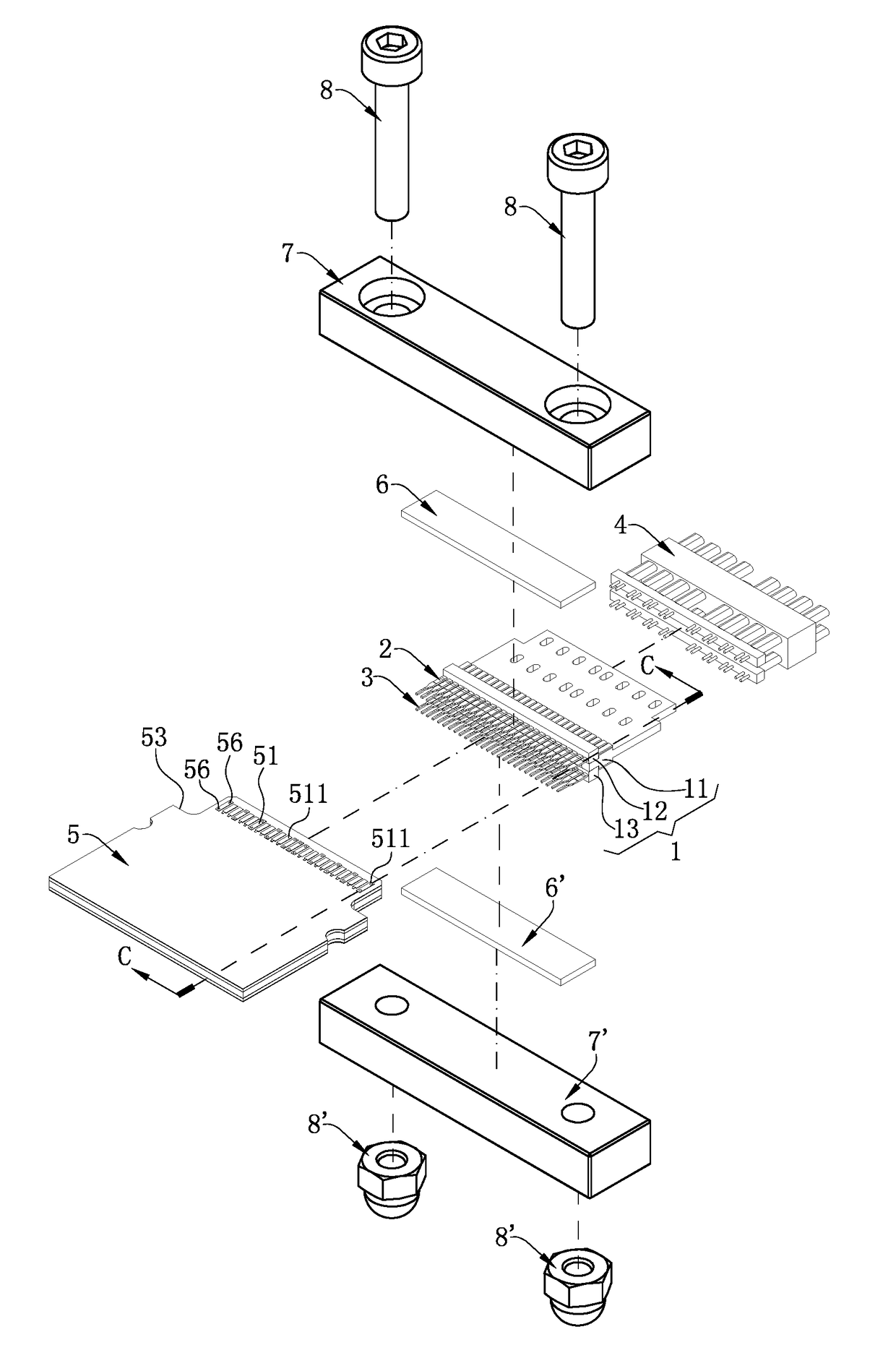
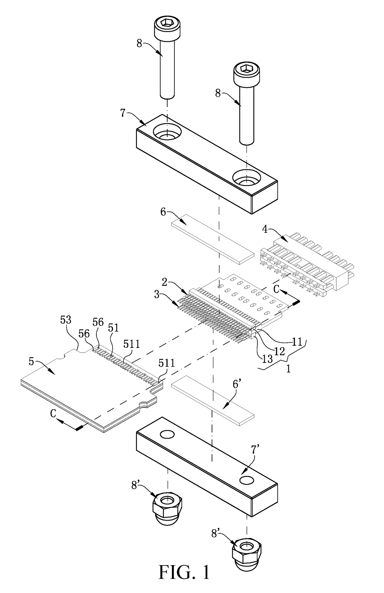
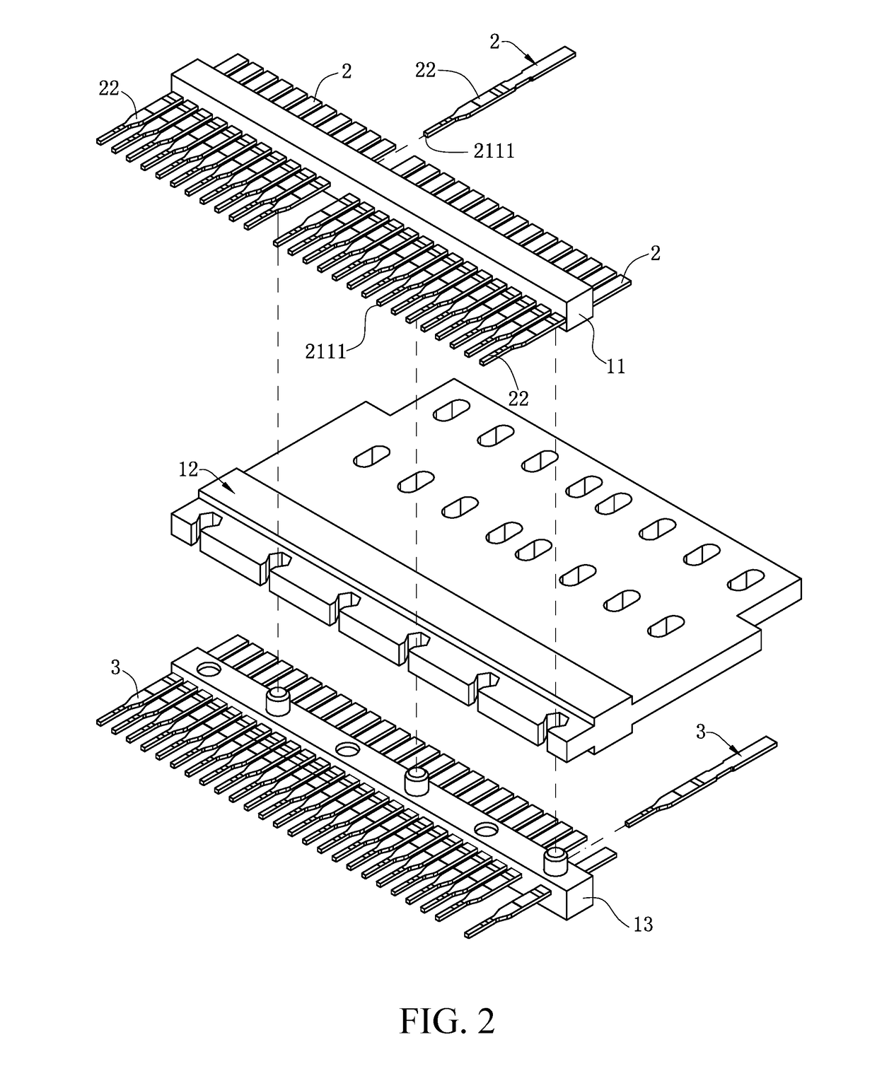
An electrical connection device has a first insulating body. A strip-shaped first conductor is accommodated in the first insulating body. The first conductor as a whole is arranged horizontally to electrically connect backward with a first docking component. A bottom surface of the first conductor has a front edge, and a contact area extends backward from the front edge. A second docking component includes a second conductor located below the first conductor. The second conductor has a front end, a rear end, and a top surface connecting the front and rear ends. An elastic body is located above the first conductor and downwardly abuts the first conductor. A pressing piece provides a downward force to make the first conductor downwardly abut the second conductor.

Description

CROSS-REFERENCE TO RELATED APPLICATION[0001]This non-provisional application claims priority to and the benefit of, pursuant to 35 U.S.C. § 119(a), Patent Application Serial No. 201720428993.1 filed in P.R. China on Apr. 24, 2017, the entire content of which is hereby incorporated by reference.FIELD OF THE INVENTION[0002]The present invention relates to an electrical connection device, and in particular to an electrical connection device for high-frequency signal transmission.BACKGROUND OF THE INVENTION[0003]In various electrical connection devices, it is common that two conductors are separably pressed and connected, such as a terminal and a terminal, a terminal and a conductive sheet, a terminal and a cable. In order to guarantee the stability of the press and connection, an elastic body is usually adopted to apply elastic force to the two conductors, as shown in a Chinese patent (Patent Number: 200520053929.7). The electrical connector shown in that Chinese patent has an elastic ...

Claims


Application Information

Patent Timeline
Patent Type & Authority Applications(United States)
IPC IPC(8): H01R13/512H01R12/72
CPCH01R13/512H01R12/721H01R12/772H01R12/7047
Inventor DAI, YONG JUNJIN, ZUO FENG
Owner LOTES
Why Eureka
Try Eureka