Eureka AIR delivers breakthrough ideas for toughest innovation challenges, trusted by R&D personnel around the world.

Differential contact module and differential connector and connector assembly using the module

A technology of differential connectors and contacts, which is applied to parts of connection devices, protective grounding/shielding devices of connection parts, connections, etc., which can solve problems such as crosstalk, unsatisfied, and signal transmission quality limitations, and improve signal transmission quality , Solve crosstalk and reduce crosstalk

Active Publication Date: 2016-03-23
CHINA AVIATION OPTICAL-ELECTRICAL TECH CO LTD
View PDF5 Cites 20 Cited by
  • Summary
  • Abstract
  • Description
  • Claims
  • Application Information

AI Technical Summary

Problems solved by technology

The high-speed, high-density electrical connector with a central shielding pin is provided with the ground contact between two adjacent differential pairs of its contact module, thereby avoiding crosstalk between differential pairs, to a certain extent The reliability of signal transmission is improved, but the problem of crosstalk between the two differential pairs through the gap between the ground contact and the upper ground contact still exists, which limits the quality of signal transmission and cannot meet the requirements of some occasions. In addition, since there is no shielding structure between adjacent two-layer contact modules, the crosstalk problem between adjacent two-layer contact modules still cannot be solved

Method used


Image

  • Differential contact module and differential connector and connector assembly using the module
  • Differential contact module and differential connector and connector assembly using the module
  • Differential contact module and differential connector and connector assembly using the module

Examples


Embodiment Construction

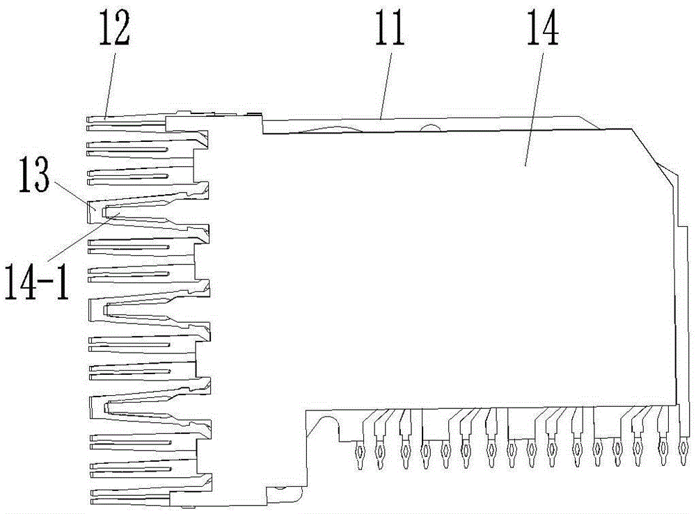
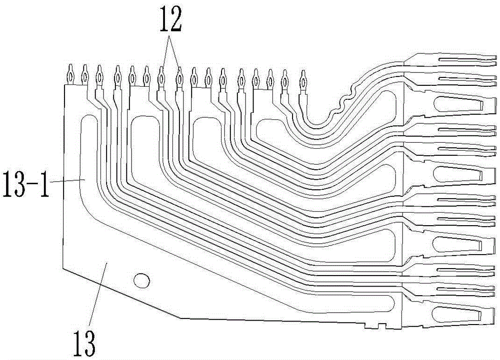
[0031] Embodiment 1 of the differential contact module of the present invention, such as Figure 1-3 As shown, it includes an insulating base 11, and the insulating base 11 is fixedly equipped with a differential pair 12 and a ground contact 13. The arrangement of the differential pair 12 and the ground contact 13 is the prior art, and will not be described here. In addition, this In the embodiment, the ground contact 13 has an upwardly protruding raised structure 13-1, and the upper side of the insulating base 11 is provided with a shielding plate 14, and the side edge of the shielding plate 14 close to the plug-in end of the contact module The conductive sheet 14 - 1 is provided and is electrically connected to the ground contact 13 through the conductive sheet 14 - 1 , so far, the ground contact 13 , the differential pair 12 and the shielding plate 14 together form a stripline structure. When in use, the path where crosstalk can occur between two adjacent differential pairs...


PUM


Abstract

The invention relates to the field of electrical connectors and particularly relates to a difference contact module and a difference connector and a connector assembly using the module. The difference contact module comprises an insulating base body, a differential pair and a grounding contact, wherein the differential pair and the grounding contact are assembled inside the insulating base body, a shielding plate is arranged above and / or below the differential pair and the grounding contact on the insulating base body, and at least one of the grounding contact and the shielding plate is provided with a protruding structure which protrudes towards the other one of the grounding contact and the shielding plate. During usage, a gap between two adjacent differential pairs, in which the crosstalk occurs, is greatly reduced, so that the crosstalk between two adjacent differential pairs of the difference connector can be reduced, and the signal transmission quality of the difference connector can be improved; besides, the shielding plate is arranged, so that two adjacent layers of difference contact modules of the difference connector are isolated, and the problem of the crosstalk between two adjacent layers of contact modules can be solved.

Description

technical field [0001] The invention relates to the field of electrical connectors, in particular to a differential contact module, a differential connector and a connector assembly using the module. Background technique [0002] Differential connectors use signal contacts to achieve signal connections between electronic devices. Usually, the distance between two adjacent signal contacts is limited, which leads to a mixed electric field that makes one signal contact between two adjacent signal contacts. Crosstalk occurs when the pins induce electrical interference, ultimately compromising signal integrity. [0003] The Chinese patent application number 2007100779307 discloses a high-speed, high-density electrical connector with a central shielding pin. The high-speed, high-density electrical connector with a central shielding pin includes an insulating base and is sequentially arranged on the More than two layers of contact modules in the insulating base, each of the contac...

Claims


Application Information

Patent Timeline
Patent Type & Authority Patents(China)
IPC IPC(8): H01R13/648
CPCH01R13/514H01R13/6471H01R13/6587
Inventor 周国奇赵越超袁俊峰
Owner CHINA AVIATION OPTICAL-ELECTRICAL TECH CO LTD
Why Eureka
Eureka Blog
Learn More