
Method and apparatus for optically measuring periodic structures using orthogonal azimuthal sample orientations

a technology of orthogonal azimuthal sample orientation and optical measurement, applied in the direction of optical radiation measurement, instruments, spectrometry/spectrophotometry/monochromators, etc., can solve the problem of other problems quickly becoming impractical to solve, and achieve the effect of reducing the computation time of the phi=90 case, and reducing the computation tim

Inactive Publication Date: 2008-06-05
JORDAN VALLEY SEMICON
View PDF57 Cites 63 Cited by
  • Summary
  • Abstract
  • Description
  • Claims
  • Application Information

AI Technical Summary

Benefits of technology

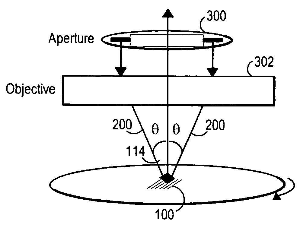
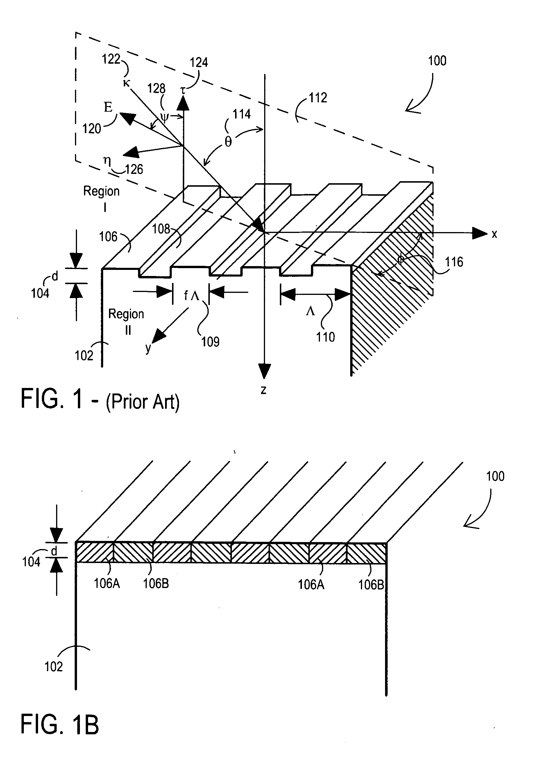
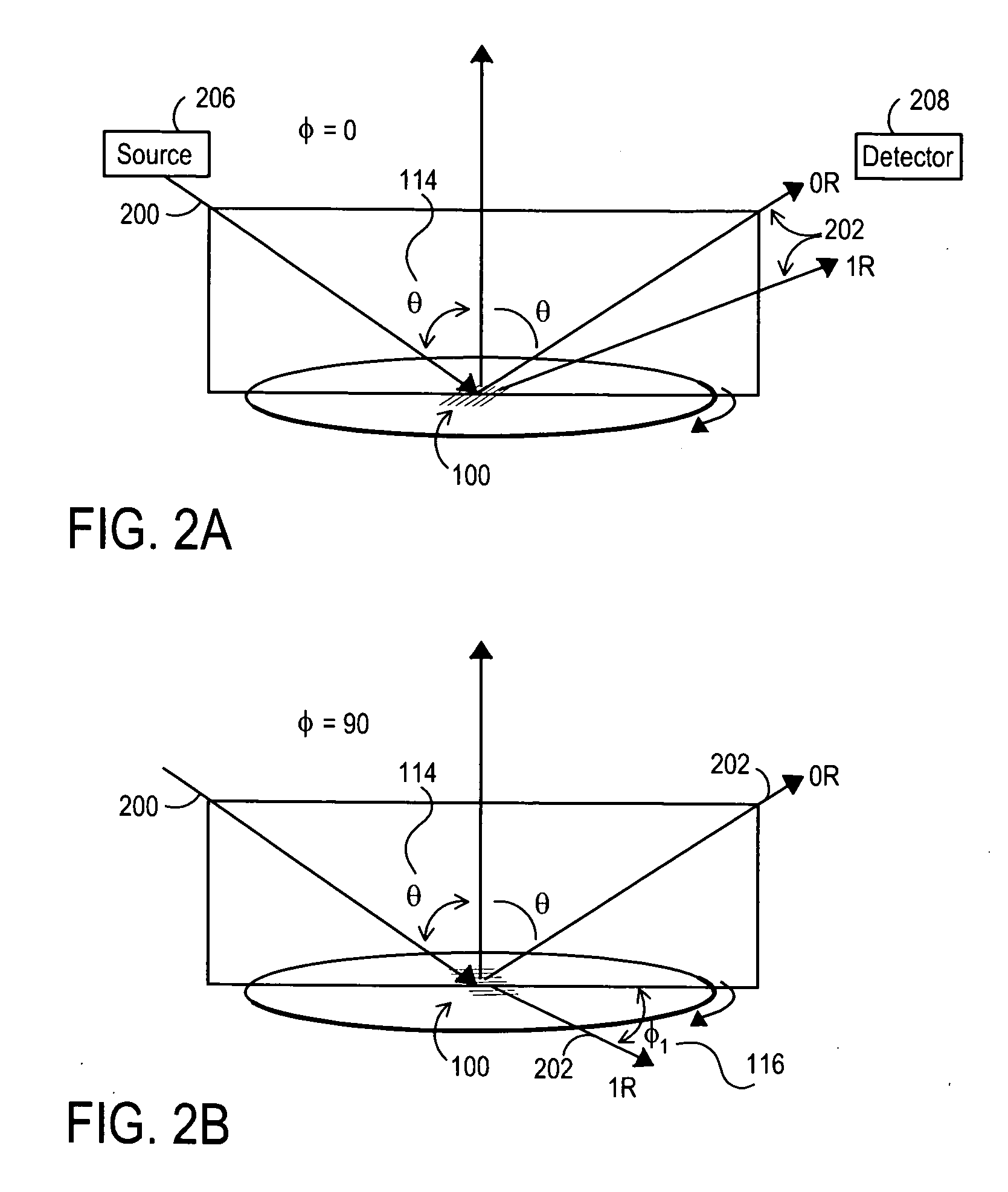
[0012]An optical metrology apparatus for measuring periodic structures using multiple incident azimuthal (phi) and polar (theta) incident angles is described. One embodiment provides the enhanced calculation speed for the special case of phi=90 incidence for 1-D (line and space) structures, which has the incident plane parallel to the grating lines, as opposed to the phi=0 classical mounting, which has incident plane perpendicular to the grating lines. The enhancement reduces the computation time of the phi=90 case to the same order as the corresponding phi=0 case, and in some cases the phi=90 case can be significantly faster. One advantageous configuration consists of two measurements for each sample structure, one perpendicular to the grating lines and one parallel. This provides additional information about the structure, equivalent to two simultaneous angles of incidence, without excessive increase in computation time. Alternately, in cases where the computation for phi=90 is faster than the corresponding phi=0 incidence, it may be advantageous to measure parallel to the grating lines only. In the case where two sets of incident angles are used, the incident light can be polarized to provide a total of four sets of data—Rs0, Rp0, Rs90, Rp90—for each incident polar angle, all from the same structure (Rs0 being a data set having incident phi=0 and incident polarization normal to the plane of incidence, Rp90 being a data set having incident phi=90 and incident polarization within the plane of incidence, etc.).
[0013]In one embodiment, the techniques described herein provide an optical metrology apparatus and methods and systems for measuring periodic structures using multiple incident azimuthal (phi) and polar (theta) angles, and particularly to enhanced calculation speed for a special case of phi=90 incidence for 1-D (line and space) structures, having an incident plane parallel to grating lines.
[0015]The method may include illuminating a grating structure with polarized or unpolarized, monochromatic or broadband light. The incident light may be at one or more polar angles, theta, at the phi=0 and phi=90 azimuthal directions for each of the polar angles. The method may further include detecting the response, for a total of up to four datasets per grating sample per incident polar angle, which are then simultaneously analyzed in order to take advantage of the enhanced information content contained in the multiple datasets. The calculation time is reduced compared to conventional RCW formulations due to the reduced calculation requirements for the phi=90 cases.

Problems solved by technology

The result is that while some diffraction problems are very tenable, others quickly become impractical to solve due to a large computation cost.

Method used


Image

  • Method and apparatus for optically measuring periodic structures using orthogonal azimuthal sample orientations
  • Method and apparatus for optically measuring periodic structures using orthogonal azimuthal sample orientations
  • Method and apparatus for optically measuring periodic structures using orthogonal azimuthal sample orientations

Examples


Embodiment Construction

[0032]One way to directly attack the time required for the RCW method is to reduce the number of spatial harmonics involved in the eigen-problem, the boundary problem, or both. This was done for the general case to a large extent in the work of Moharam and Gaylord in their papers: M. G. Moharam, E. B. Grann, D. A. Pommet, and T. K. Gaylord, “Formulation for stable and efficient implementation of the rigorous coupled-wave analysis of binary gratings,” J. Opt. Soc. Am. A 12, 1068-1076 (1995) and M. G. Moharam, D. A. Pommet, E. B. Grann, and T. K. Gaylord, “Stable implementation of the rigorous coupled-wave analysis for surface-relief gratings: enhanced transmittance matrix approach,” J. Opt. Soc. Am. A 12, 1077-1086 (1995). Subsequent modifications to enhance the TM convergence have included those techniques shown in: P. Lalanne and G. M. Morris, “Highly improved convergence of the coupled-wave method for TM polarization,” J. Opt. Soc. Am. A 13, 779-784 (1996); G. Granet and B. Guizal...


PUM


Abstract

An optical metrology apparatus for measuring periodic structures using multiple incident azimuthal (phi) and polar (theta) incident angles is described. One embodiment provides the enhanced calculation speed for the special case of phi=90 incidence for 1-D (line and space) structures, which has the incident plane parallel to the grating lines, as opposed to the phi=0 classical mounting, which has incident plane perpendicular to the grating lines. The enhancement reduces the computation time of the phi=90 case to the same order as the corresponding phi=0 case, and in some cases the phi=90 case can be significantly faster. One advantageous configuration consists of two measurements for each sample structure, one perpendicular to the grating lines and one parallel. This provides additional information about the structure, equivalent to two simultaneous angles of incidence, without excessive increase in computation time. Alternately, in cases where the computation for phi=90 is faster than the corresponding phi=0 incidence, it may be advantageous to measure parallel to the grating lines only. In the case where two sets of incident angles are used, the incident light can be polarized to provide a total of four sets of data—Rs0, Rp0, Rs90, Rp90—for each incident polar angle, all from the same structure.

Description

[0001]This application claims priority to Provisional Patent Application No. 60 / 872,010 filed Nov. 30, 2006; the disclosure of which is expressly incorporated herein by reference in its entirety.TECHNICAL FIELD OF THE INVENTION[0002]This invention relates to an optical metrology apparatus and methods and systems for measuring periodic structures using multiple incident azimuthal (phi) and polar (theta) angles, and particularly to enhanced calculation speed for a special case of phi=90 incidence for 1-D (line and space) gratings, having an incident plane parallel to grating lines. This results in additional datasets to supplement data collected in the phi=0 classical mount configuration without an untenable increase in computation cost.BACKGROUND OF THE INVENTION[0003]A widely referenced source on a rigorous coupled wave (RCW) algorithm is that of Moharam and Gaylord (M. G. Moharam, E. B. Grann, D. A. Pommet, and T. K. Gaylord, J. Opt. Soc., Am. A, Vol. 12, No. 5, p. 1068 (1995)). A ...

Claims


Application Information

Patent Timeline
Patent Type & Authority Applications(United States)
IPC IPC(8): G01B11/26G01J3/18
CPCG01B11/24G01N21/211G01N21/4788
Inventor WALSH, PHILLIP
Owner JORDAN VALLEY SEMICON
Learn More