
Image stabilization techniques and methods

a technology of image stabilization and control system, applied in the field of catheter control system and method, can solve the problems of difficult manipulation, lack of therapeutic treatment capability of conventional catheter imaging system, and general difficulty in heart disease treatment in a patient's heart, and achieve the effect of simplifying the output imag

Active Publication Date: 2012-01-19
INTUITIVE SURGICAL OPERATIONS INC
View PDF14 Cites 71 Cited by
  • Summary
  • Abstract
  • Description
  • Claims
  • Application Information

AI Technical Summary

Benefits of technology

[0009]Accordingly, various methods and techniques may be effected to stabilize the images of the tissue when directly visualizing moving regions of tissue, such as the tissue which moves in a beating heart with an imaging assembly positioned in proximity to or against the tissue. Systems and mechanisms are described that can capture and process video images in order to provide a “stabilized” output image and / or create a larger composite image generated from a series of images for the purposes of simplifying the output image for user interpretation during diagnostic and therapeutic procedures.
[0010]Typically, images can be captured / recorded by a video camera at a rate of, e.g., 10-100 fps (frames per second), based on the system hardware and software configurations. Much higher video capture rates are also possible in additional variations. The images can then be captured and processed with customizable and / or configurable DSP (digital signal processing) hardware and software at much higher computational speeds (e.g., 1.5-3 kHz as well as relatively slower or faster rates) in order to provide real-time or near real-time analysis of the image data. Additionally, analog signal processing hardware may also be incorporated. A variety of algorithms, e.g., optical flow, image pattern matching, etc. can be used to identify, track and monitor the movement of whole images or features, elements, patterns, and / or structures within the image(s) in order to generate velocity and / or displacement fields that can be utilized by further algorithmic processing to render a more stabilized image. For the imaging assembly, examples of various algorithms which may be utilized may include, e.g., optical flow estimation to compute an approximation to the motion field from time-varying image intensity. Additionally, methods for evaluating motion estimation may also include, e.g., correlation, block matching, feature tracking, energy-based algorithms, as well as, gradient-based approaches, among others.
[0011]In some cases, the image frames may be shifted by simple translation and / or rotation and may not contain a significant degree of distortion or other artifacts to greatly simplify the image processing methods and increase overall speed. Alternatively, the hardware and software system can also create a composite image that is comprised (or a combination) of multiple frames during a motion cycle by employing a variety of image stitching algorithms. A graphical feature, e.g., a circle, square, dotted-lines, etc, can be superimposed or overlaid on the composite image in order to indicate the actual position of the camera (image) based on the information obtained from the image tracking software as the camera / hood undergoes a certain excursion, displacement, etc., relative to the target tissue of the organ structure.
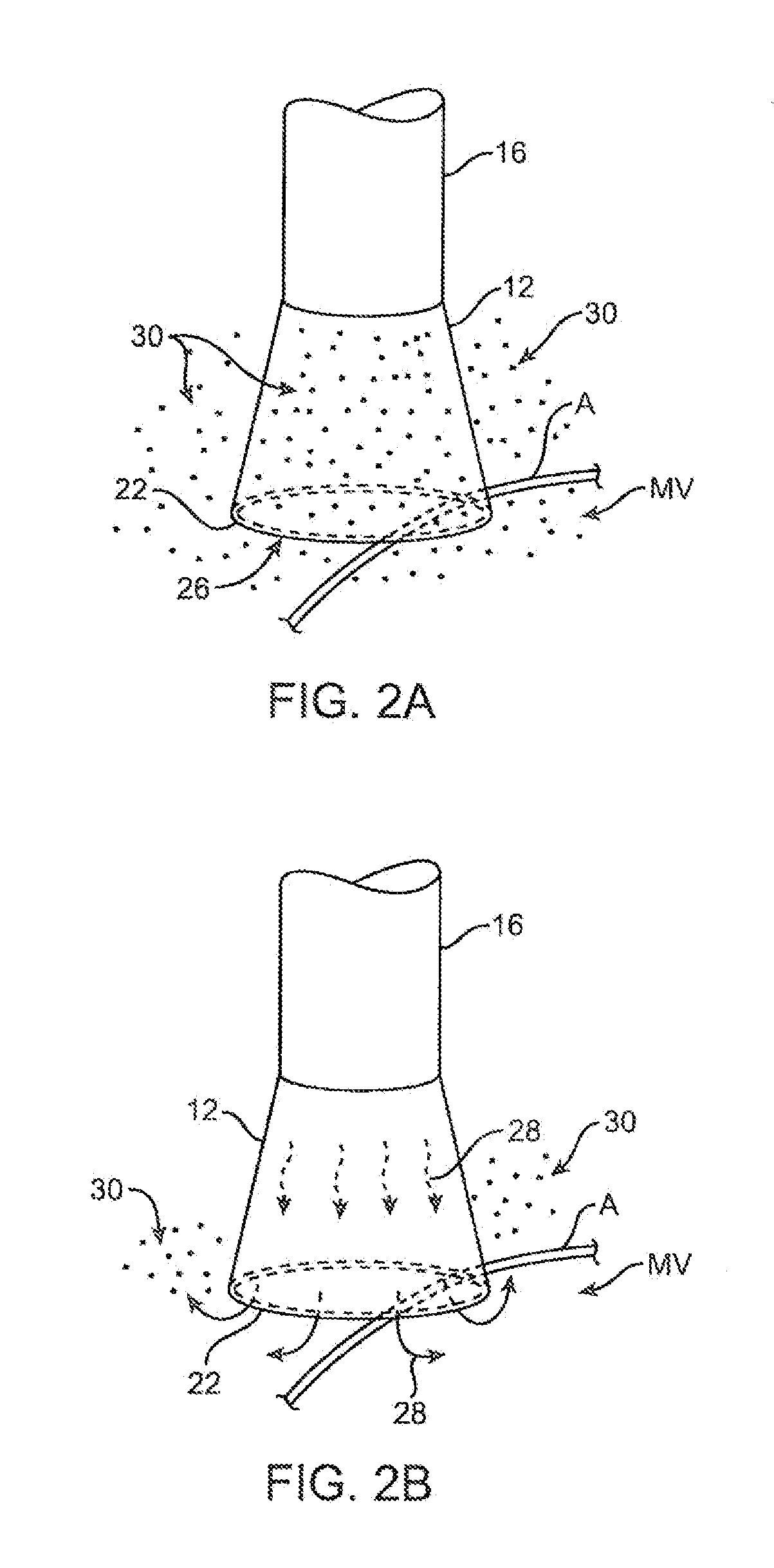
[0015]As the camera actively tracks its position relative to the target tissue, the power delivered by the RF generator during ablation may also be controlled as a function of the position of the hood in order to deliver energy to the tissue at a consistent level. In situations where the excursions of the hood / camera occur with varying velocity, the power level may be increased during periods of rapid movements and / or decreased during periods of slower movements such that the average delivery of energy per region / area (per unit time) is roughly constant to minimize regions of incomplete or excessive ablation thus potentially reducing or eliminating damage to surrounding tissue, structures or organs. Alternatively, the tracking of the target tissue may be utilized such that only particular regions in the moving field receive energy whereas other areas in the field receive none (or relatively less energy) by modulating the output power accordingly by effectively gating the power delivery to a location(s) on the target tissue. This technique could ultimately provide higher specificity and focal delivery of ablative energy despite a moving RF electrode system relative to the target tissue.

Problems solved by technology

However, many of the conventional catheter imaging systems lack the capability to provide therapeutic treatments or are difficult to manipulate in providing effective therapies.
For instance, the treatment in a patient's heart for atrial fibrillation is generally made difficult by a number of factors, such as visualization of the target tissue, access to the target tissue, and instrument articulation and management, amongst others.
Conventional catheter techniques and devices, for example such as those described in U.S. Pat. Nos. 5,895,417; 5,941,845; and 6,129,724, used on the epicardial surface of the heart may be difficult in assuring a transmural lesion or complete blockage of electrical signals.
In addition, current devices may have difficulty dealing with varying thickness of tissue through which a transmural lesion is desired.
Conventional accompanying imaging devices, such as fluoroscopy, are unable to detect perpendicular electrode orientation, catheter movement during the cardiac cycle, and image catheter position throughout lesion formation.
The absence of real-time visualization also poses the risk of incorrect placement and ablation of structures such as sinus node tissue which can lead to fatal consequences.
Moreover, because of the tortuous nature of intravascular access, devices or mechanisms at the distal end of a catheter positioned within the patient's body, e.g., within a chamber of the heart, are typically no longer aligned with the handle.
Steering or manipulation of the distal end of the catheter via control or articulation mechanisms on the handle is easily disorienting to the user as manipulation of a control on the handle in a first direction may articulate the catheter distal end in an unexpected direction depending upon the resulting catheter configuration leaving the user to adjust accordingly.
However, this results in reduced efficiency and longer procedure times as well as increased risks to the patient.

Method used


Image

  • Image stabilization techniques and methods
  • Image stabilization techniques and methods
  • Image stabilization techniques and methods

Examples


Embodiment Construction

[0046]A tissue-imaging and manipulation apparatus described herein is able to provide real-time images in vivo of tissue regions within a body lumen such as a heart, which is filled with blood flowing dynamically therethrough and is also able to provide intravascular tools and instruments for performing various procedures upon the imaged tissue regions. Such an apparatus may be utilized for many procedures, e.g., facilitating transseptal access to the left atrium, cannulating the coronary sinus, diagnosis of valve regurgitation / stenosis, valvuloplasty, atrial appendage closure, arrhythmogenic focus ablation, among other procedures. Although intravascular applications are described, other extravascular approaches or applications may be utilized with the devices and methods herein.

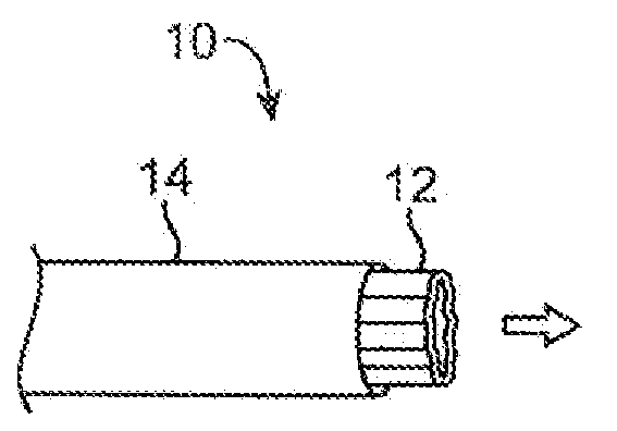
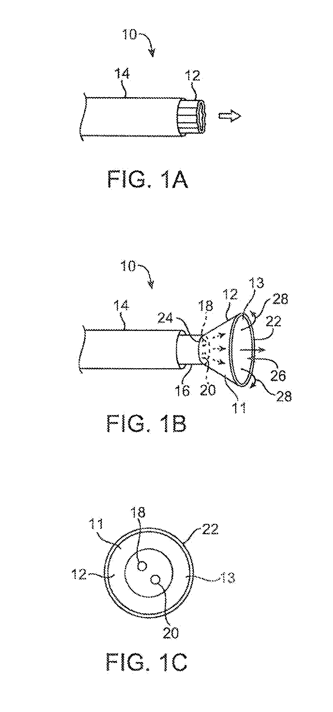
[0047]One variation of a tissue access and imaging apparatus is shown in the detail perspective views of FIGS. 1A to 1C. As shown in FIG. 1A, tissue imaging and manipulation assembly 10 may be delivered intr...


PUM


Abstract

Direct optical imaging of anatomical features and structures from within a biological organ in a dynamic environment (where the tissue being imaged is in motion due to cardiac rhythms, respiration, etc) presents certain image stability issues due (and / or related) to the motion of the target structure and may limit the ability of the user to visually interpret the image for the purposes of diagnostics and therapeutics. Systems and mechanisms for the purpose of actively stabilizing the image or for compiling and re-displaying the image information in a manner that is more suitable to interpretation by the user are disclosed.

Description

CROSS-REFERENCE TO RELATED APPLICATIONS[0001]This application claims the benefit of priority to U.S. Provisional Application 61 / 304,235 filed Feb. 12, 2010, which is incorporated herein by reference in its entirety.FIELD OF THE INVENTION[0002]The present invention relates generally to catheter control systems and methods for stabilizing images of moving tissue regions such as a heart which are captured when intravascularly accessing and / or treating regions of the body.BACKGROUND OF THE INVENTION[0003]Conventional devices for accessing and visualizing interior regions of a body lumen are known. For example, various catheter devices are typically advanced within a patient's body, e.g., intravascularly, and advanced into a desirable position within the body. Other conventional methods have utilized catheters or probes having position sensors deployed within the body lumen, such as the interior of a cardiac chamber. These types of positional sensors are typically used to determine the m...

Claims


Application Information

Patent Timeline
IPC IPC(8): A61B6/00
CPCA61B1/00009A61B1/00089A61B1/0607A61B1/0623A61B1/126A61B2562/245A61B5/1128A61B2562/0219A61B2505/05A61B2560/0204A61B2562/0233A61B5/1114A61B1/000094
Inventor SAADAT, VAHIDDREWS, MICHAEL J.
Owner INTUITIVE SURGICAL OPERATIONS INC
Learn More