
Projection Optical System, Exposure Equipment and Exposure Method

Inactive Publication Date: 2008-05-29
NIKON CORP
View PDF11 Cites 2 Cited by
  • Summary
  • Abstract
  • Description
  • Claims
  • Application Information

AI Technical Summary

Benefits of technology

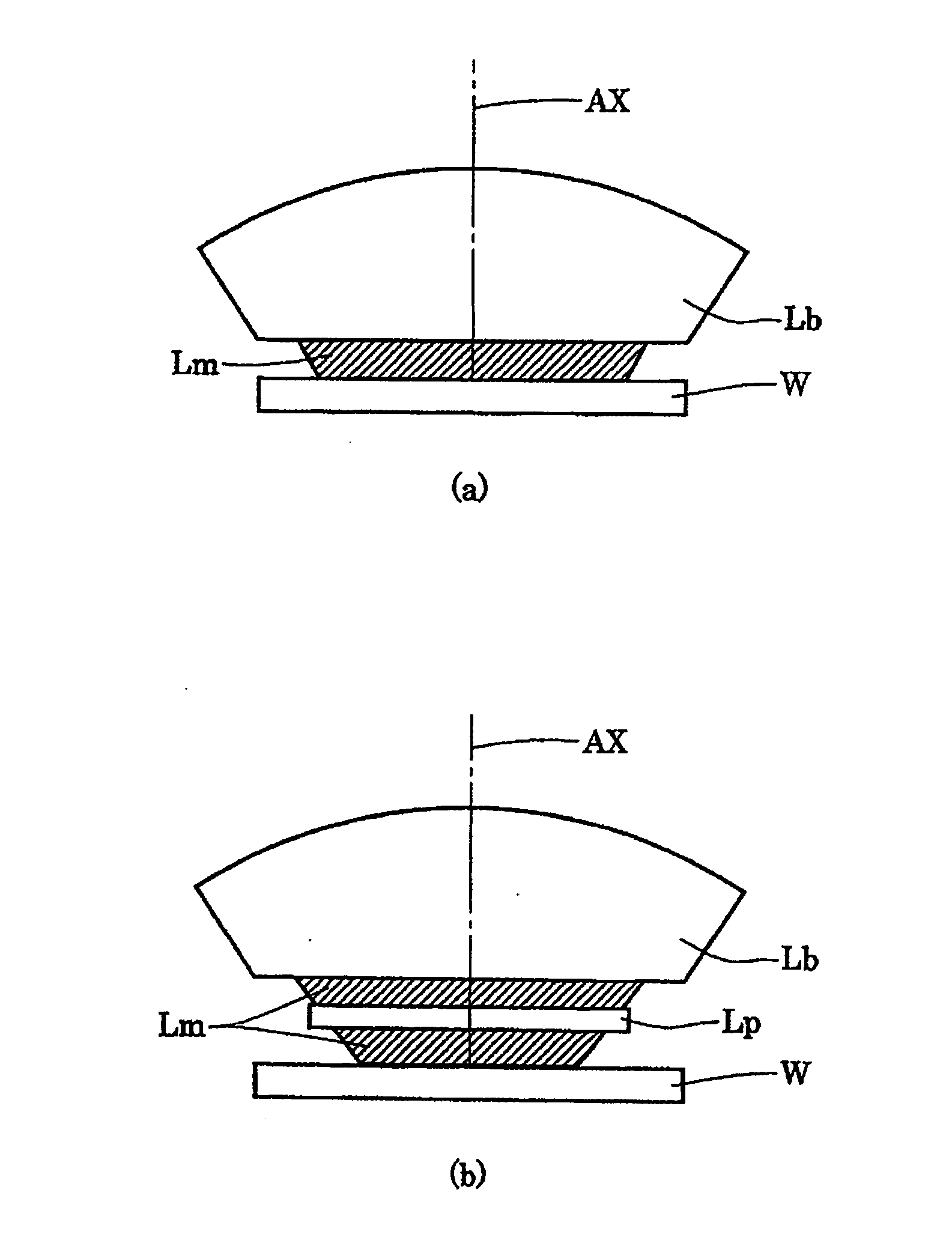
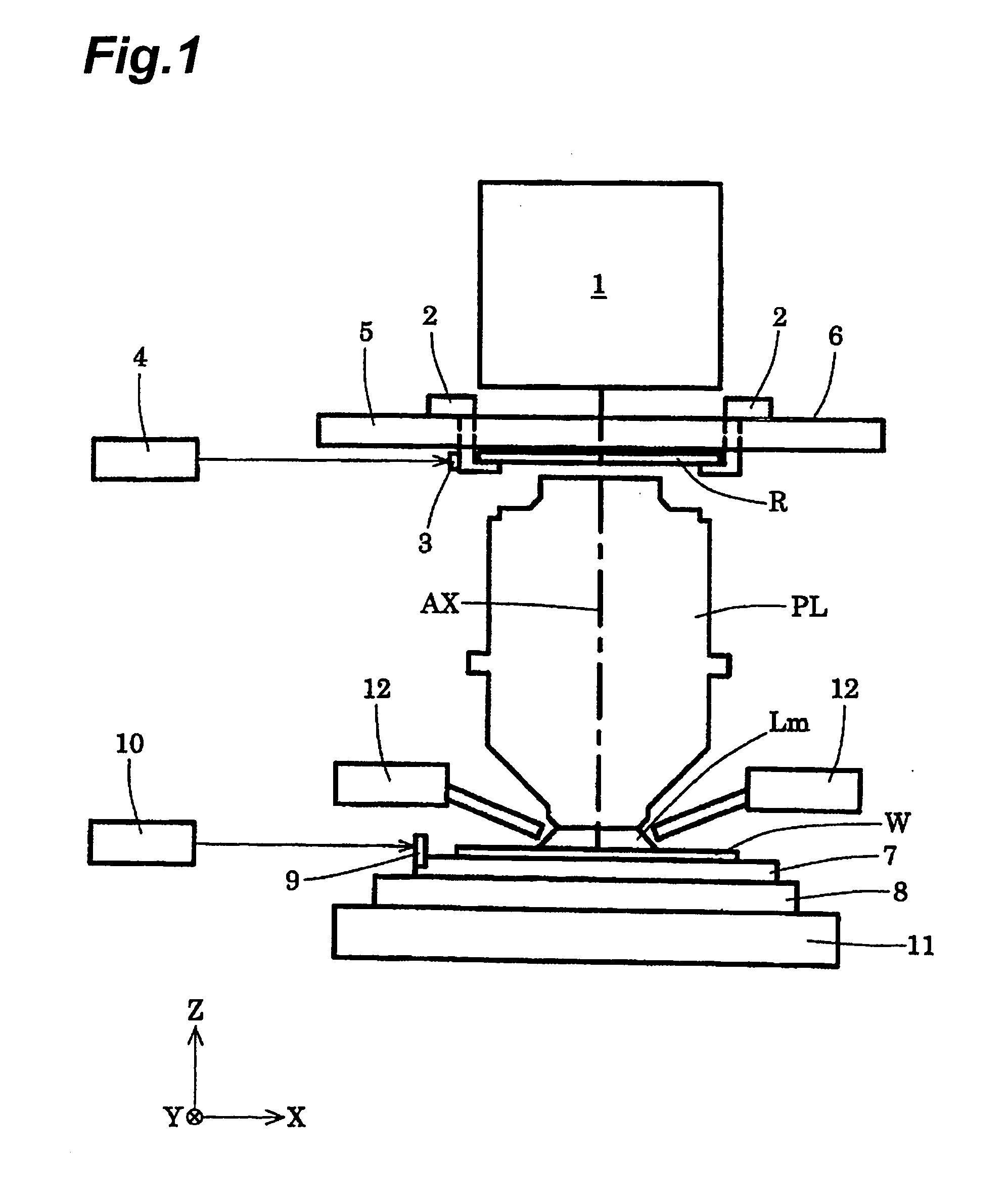
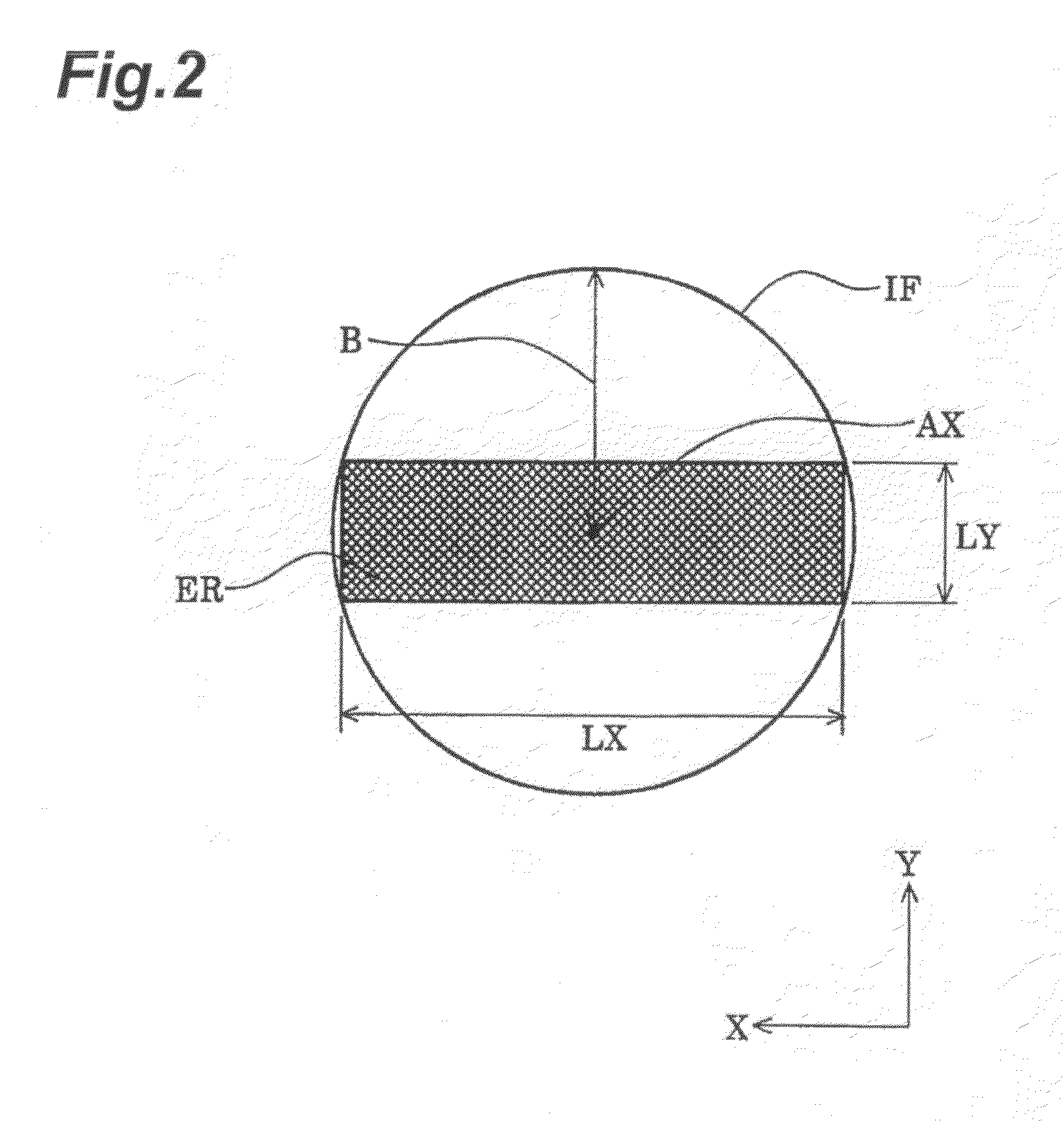
[0008]An embodiment of the present invention provides a projection optical system with good imaging performance based on well-balanced compensation for the aberration associated with image height and the aberration associated with numerical aperture, while ensuring a large effective image-side numerical aperture in the presence of a liquid in the optical path between the projection optical system and the image plane. It is another embodiment of the present invention provides an exposure apparatus and exposure method capable of performing faithful projection exposure with high resolution, using the projection optical system with good imaging performance while ensuring a large effective image-side numerical aperture.

Problems solved by technology

In this case, when one attempts to increase the image-side numerical aperture by increase in the maximum incidence angle θ, it will result in increase in incidence angles to the photosensitive substrate and in exiting angles from the projection optical system, so as to make compensation for aberration difficult, and it will eventually fail to ensure a large effective image-side numerical aperture without increase in lens sizes.

Method used


Image

  • Projection Optical System, Exposure Equipment and Exposure Method
  • Projection Optical System, Exposure Equipment and Exposure Method
  • Projection Optical System, Exposure Equipment and Exposure Method

Examples


first example

[0079]FIG. 4 is a drawing showing a lens configuration of a projection optical system according to the first example of the present embodiment. With reference to FIG. 4, the projection optical system PL of the first example is composed of the following elements named in order from the reticle side: first lens unit G1, second lens unit G2 with a positive refractive power, third lens unit G3 with a negative refractive power, fourth lens unit G4 with a positive refractive power, and fifth lens unit G5 with a positive refractive power.

[0080]The first lens unit G1 is composed of the following elements named in order from the reticle side: plane-parallel plate P1, biconcave lens L1 (first lens) a concave surface of an aspherical shape of which is directed toward the wafer, negative meniscus lens L2 (first meniscus lens) a concave surface of which is directed toward the reticle, positive meniscus lens L3 (second meniscus lens) a concave surface of an aspherical shape of which is directed t...

second example

[0086]FIG. 6 is a drawing showing a lens configuration of a projection optical system according to a second example of the present embodiment. With reference to FIG. 6, the projection optical system PL of the second example is composed of the following elements named in order from the reticle side: first lens unit G1, second lens unit G2 with a positive refractive power, third lens unit G3 with a negative refractive power, fourth lens unit G4 with a positive refractive power, and fifth lens unit G5 with a positive refractive power.

[0087]The first lens unit G1 is composed of the following elements named in order from the reticle side: plane-parallel plate P1, biconcave lens L1 (first lens) a concave surface of an aspherical shape of which is directed toward the wafer, negative meniscus lens L2 (first meniscus lens) a concave surface of which is directed toward the reticle, positive meniscus lens L3 (second meniscus lens) a concave surface of an aspherical shape of which is directed t...


PUM


Abstract

A projection optical system is a system with good imaging performance based on well-balanced compensation for aberration associated with image height and aberration associated with numerical aperture, while ensuring a large effective image-side numerical aperture in the presence of a liquid in the optical path between the projection optical system and an image plane. The projection optical system forms an image of a first plane on a second plane. An optical path between an optical member located nearest to the second plane out of optical members with a refractive power in the projection optical system, and the second plane is fillable with a predetermined liquid. The projection optical system satisfies the condition of 0.02<NA×WD / FA<0.08, where NA is a numerical aperture on the second plane side of the projection optical system, WD a distance along the optical axis between an optical member located nearest to the first plane in the projection optical system, and the first plane, and FA a maximum of effective diameters of all optical surfaces in the projection optical system.

Description

CROSS-REFERENCE TO RELATED APPLICATIONS[0001]This application is based upon and claims the benefit of priorities from International Application No. PCT / JP2005 / 019689 filed on Oct. 26, 2005, and Japanese Patent Application No. 2004-326141 filed on Nov. 10, 2004, the entire contents of which are incorporated herein by reference.BACKGROUND[0002]1. Field[0003]One embodiment of the present invention relates to a projection optical system, exposure apparatus, and exposure method and, more particularly, to a projection optical system suitably applicable to exposure apparatus used in manufacturing microdevices, such as semiconductor devices and liquid-crystal display devices, for example, by photolithography.[0004]2. Description of the Related Art[0005]The photolithography for manufacturing the semiconductor devices or the like is carried out using an exposure apparatus for projecting a pattern image of a mask (or reticle) through a projection optical system onto a photosensitive substrate ...

Claims


Application Information

Patent Timeline
IPC IPC(8): G03B27/72G01B11/02G03B27/52
CPCG02B13/143G02B13/22G03F7/706G03F7/70241G03F7/70341G02B13/24
Inventor FUJISHIMA, YOUHEI
Owner NIKON CORP
Learn More