
Laser desorption device, mass spectrometer assembly, and method for ambient liquid mass spectrometry

a mass spectrometry and desorption device technology, applied in the field of mass spectrometry, can solve the problems of low ionization efficiency, easy interference by noise signals, and low ratio of ionized analytes

Inactive Publication Date: 2008-05-22
NAT SUN YAT SEN UNIV
View PDF10 Cites 33 Cited by
  • Summary
  • Abstract
  • Description
  • Claims
  • Application Information

AI Technical Summary

Benefits of technology

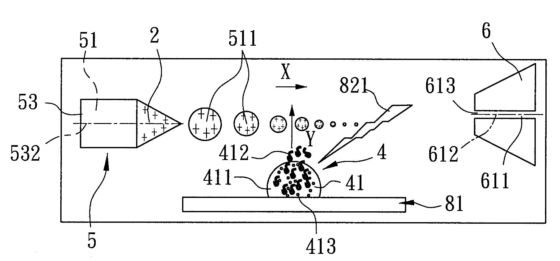
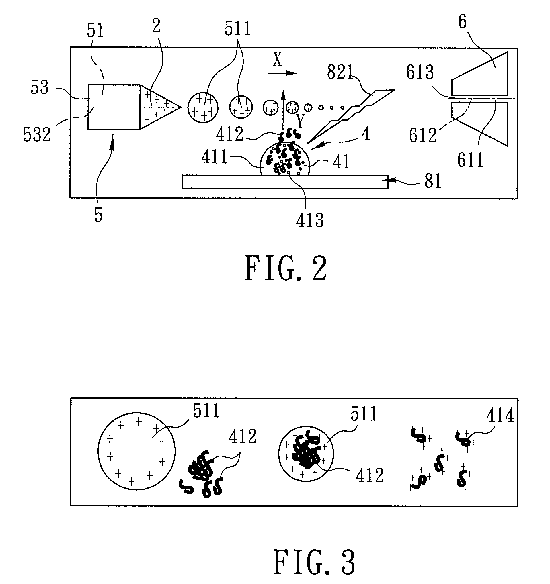
"The present invention provides a laser desorption device, a mass spectrometer assembly, and a method for mass spectrometry that can conduct mass analysis directly on a liquid sample under atmospheric pressure. The device includes a sample stage, an electrospray unit, a receiving unit, and a laser transmission mechanism. The method involves placing a liquid sample on the sample stage, using the electrospray unit to form liquid drops, using the receiving unit to admit the ionized analytes, and using the laser beam to desorb the analytes and form them into the multiple-charged liquid drops. The device and method can be used in various mass spectrometer assemblies for accurate and efficient analysis of liquid samples."

Problems solved by technology

It is widely recognized that among the analytes desorbed by the laser beam, the number of neutral analytes far exceeds the number of ionized analytes; that is, ionization efficiency is extremely low.
The signal resulted from this extremely low ratio of ionized analytes is too small and is therefore easily interfered by noise signals.
At the same time, detection sensitivity and reconstruction ability of the signals are poor such that results of the mass spectrometric analysis is relatively less reliable, and is therefore hardly determinative.
Consequently, a complicated ion peak configuration results in the mass spectrum, where some ion peaks are produced by the protein molecules that are ionized through acquiring charges from the salts, making it difficult to determine the identity of these ion peaks.
Even with the assistance of a computer software, no accuracy in the molecular weight calculations of the proteins and the determination of the identities of the proteins is promisable.
However, professional personnel are required to execute the “desalination” pre-process, which is a tedious, time consuming and very inconvenient process.
Then, a laser beam is irradiated on the surface of the crystal by a laser transmission device, causing ionization and desorption of the protein molecules.
However, the resolution of MALDI-MS is poor, and due to the small amount of protein molecules (analyte) available, the desorption process of MALDI-MS needs to be conducted in vacuum.
This not only increases the cost of instrumentation, but is also inconvenient as switching between vacuum / atmospheric pressure environments during replacement of samples requires a number of tedious instrumental operations.
However, since under a lot of circumstances, the samples, such as body fluids (e.g., urine, blood), are in liquid form to begin with, it is rather inconvenient and time consuming to transform the liquid samples into solid samples in order to perform mass spectrometric analysis, especially when the number of samples to be analyzed is quite large.
Even though this special type of MALDI-MS method is capable of conducting mass spectrometric analysis on a liquid sample, a vacuum environment is still required.
Moreover, a highly viscous solute, such as glycerin, is required for preparing the liquid sample, keeping the cost of instrumentation high and preparation of the sample tedious.
In addition, the liquid state matrix can only be used for analyzing samples with molecular weights under 30,000, making application of SALDI-MS limited.
It can be seen from the above that conducting protein analysis directly on a liquid sample using mass spectrometry techniques presents a variety of difficulties and inconveniences.

Method used


Image

  • Laser desorption device, mass spectrometer assembly, and method for ambient liquid mass spectrometry
  • Laser desorption device, mass spectrometer assembly, and method for ambient liquid mass spectrometry
  • Laser desorption device, mass spectrometer assembly, and method for ambient liquid mass spectrometry

Examples


second preferred embodiment

[0166]With reference to FIG. 5, the second preferred embodiment of a mass spectrometer assembly implementing the method of ambient liquid mass spectrometry according to the present invention is similar to the first preferred embodiment. The only difference between the first and second preferred embodiments is that the electrospray unit 5′ of the second preferred embodiment further includes an airstream supplying mechanism 55′ for accelerating vaporization of the multiple-charged liquid drops 511 (refer to FIGS. 2 to 4) to result in dwindling in size thereof when approaching the mass analyzer 61 (refer to FIG. 5) along the traveling path (X). The airstream supplying mechanism 55′ surrounds the nozzle 53, and supplies a nitrogen airstream 551′. In particular, the temperature of the nitrogen airstream 551′ can be controlled by the user between the room temperature and 325° C. as is required.

third preferred embodiment

[0167]As shown in FIG. 6, the third preferred embodiment of a mass spectrometer assembly implementing the method of ambient liquid mass spectrometry according to the present invention is similar to the first preferred embodiment. The difference between the first and third preferred embodiments is that the nozzle 53″ of the electrospray unit 5″ of the third preferred embodiment is made from a non-metal material, and the electrospray unit 5″ further includes a micro-tube 56″. The micro-tube 56″ includes a tubular body 561″ connected between and disposed in fluid communication with the pump 54 and the nozzle 53″, and a center portion 562″ connected to the tubular body 561″ and coupled to the voltage supplying member 3 (refer to FIG. 4) such that the potential difference is established between the micro-tube 56″ and the mass analyzer 61 of the receiving unit 6.

fourth preferred embodiment

[0168]Referring to FIG. 7, the fourth preferred embodiment of a mass spectrometer assembly implementing the method of ambient liquid mass spectrometry according to the present invention is similar to the first preferred embodiment. The difference between the first and fourth preferred embodiments is that the sample stage 81′″ of the laser desorption device 8′″ includes a movable track 814′″, and a support member set 815′″ including a plurality of support members 816′″ (only one is visible in FIG. 7) connected in sequence and mounted movably on the track 814′″.

[0169]To conduct mass spectrometric analysis using the mass spectrometer assembly of the fourth preferred embodiment, a plurality of liquid samples 4 (as shown in FIG. 4) are first contained in containers 10 (e.g., test tubes or centrifuge tubes) (only one is visible in FIG. 7), respectively. Subsequently, each of the containers 10 is disposed on a corresponding one of the support members 816′″. Through control of a computer so...


PUM


Abstract

An electrospray-assisted laser desorption ionization device includes: an electrospray unit including a nozzle; a voltage supplying member disposed to establish between the nozzle and a receiving unit a potential difference such that liquid drops of the electrospray medium formed at the nozzle are laden with charges, and such that the liquid drops are forced to leave the nozzle toward the receiving unit along a traveling path; a laser desorption unit adapted to irradiate a sample such that, upon irradiation, analytes contained in the sample are desorbed to fly along a flying path which intersects the traveling path so as to enable the analytes to be occluded in the liquid drops, and such that as a result of dwindling in size of the liquid drops when moving along the traveling path, charges of the liquid drops will pass on to the analytes occluded therein to form ionized analytes.

Description

CROSS-REFERENCE TO RELATED APPLICATION[0001]This application is a continuation-in-part (CIP) of U.S. patent application Ser. No. 11 / 561,131, entitled “ELECTROSPRAY-ASSISTED LASER DESORPTION IONIZATION DEVICE, MASS SPECTROMETER, AND METHOD FOR MASS SPECTROMETRY”, filed on Nov. 17, 2006.BACKGROUND OF THE INVENTION[0002]1. Field of the Invention[0003]The invention relates to a method for mass spectrometry, more particularly to a method for ambient liquid mass spectrometry that is capable of conducting direct analysis of mass spectrometry on a liquid sample under atmospheric pressure. In addition, the present invention also relates to a laser desorption device that is adapted for use with a receiving unit, an electrospray unit, and a voltage supplying member in a mass spectrometer so as to conduct ambient liquid mass spectrometry. Further, the present invention relates to a mass spectrometer assembly incorporating the laser desorption device.[0004]2. Description of the Related Art[0005]...

Claims


Application Information

Patent Timeline
Patent Type & Authority Applications(United States)
IPC IPC(8): B01D59/44H01J27/02
CPCH01J49/165H01J49/0463
Inventor SHIEA, JENTAIEYUAN, CHENG-HUI
Owner NAT SUN YAT SEN UNIV
Learn More