Reaction device, and fuel cell device and electronic apparatus using the reaction device
a technology of reaction device and fuel cell, which is applied in the direction of electrochemical generator, sustainable manufacturing/processing, chemical/physical/physico-chemical processes, etc., can solve the problems of reducing the strength of the junction of the pipe, the problem of hydrogen's handling and storage, etc., and achieves the effect of high infrared absorption
- Summary
- Abstract
- Description
- Claims
- Application Information
AI Technical Summary
Benefits of technology
Problems solved by technology
Method used
Image
Examples
first embodiment
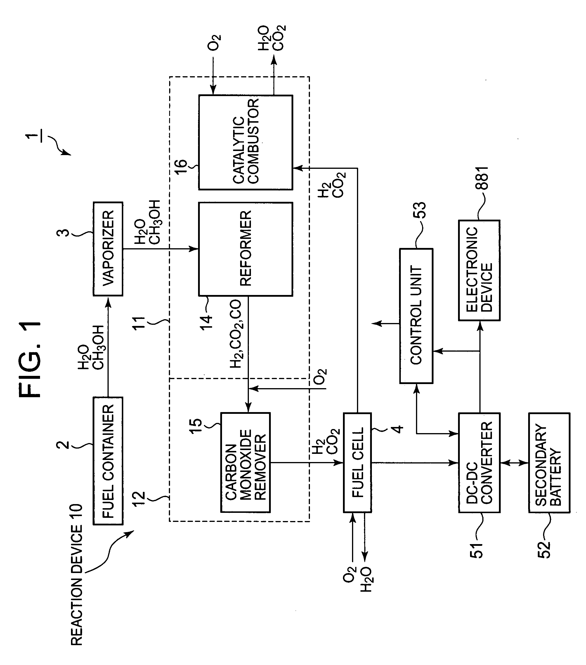
[0038]FIG. 1 is a block diagram of a fuel cell device 1, to which the present invention is applied. The fuel cell device 1 is installed in an electronic apparatus such as a lap-top personal computer, a portable telephone, a personal digital assistant (PDA), an electronic personal organizer, a wrist watch, a digital still camera, a digital video camera, game equipment, an amusement machine, and the like, and is used as the power source for operating the electric device main body 881.
[0039]The fuel cell device 1 includes a fuel container 2, a vaporizer 3, a reaction device 10, a fuel cell 4, a DC-DC converter 51 converting the electric energy generated by the fuel cell 4 to a suitable voltage, a secondary battery 52 connected to the DC-DC converter 51, and a control unit 53 controlling the above units. The fuel container 2 reserves a fuel such as methanol, ethanol, butane or the like and water in the state of being separated or being mixed, and supplies the vaporized mixed liquid of t...
embodiment a
[0058]For example, as shown in FIG. 2A, a heat dissipation acceleration portion 40a can be formed by the further formation of an absorbing film 32 absorbing infrared rays on the inner side of the reflection film 31 provided on the inner wall surface of the heat insulating container 30 where the pipe 22 penetrates the heat insulating container 30. The adiabatic effect can be secured by the reflection film 31, and the steep temperature changes at positions near the joining areas of the pipe 22 where the heat dissipation acceleration portion 40a is formed can be suppressed by the heat dissipation acceleration portion 40a to reduce the thermal stress.
embodiment b
[0059]Moreover, as shown in FIG. 2B, a heat dissipation acceleration portion 40b may be formed by providing the absorbing film 32 not in the neighborhoods of the penetration portions of the pipe 22, but on the wall a little distant from the penetration portions within the same plane of the inner wall where the pipe 22 penetrates. The absorbing film 32 may be provided at two positions so as to sandwich the penetration portions between them, for example, or may be provided so as to enclose the penetration portions.
[0060]By disposing the absorbing films 32 in such a way, a heat quantity is conducted from the reaction device 10 to the by the pipe 22, and the infrared rays radiated from the reaction device 10 are absorbed by the absorbing films 32 formed on the wall distant from the penetration portions of the pipe 22 by a little to be transmitted to the heat insulating container 30 as a radiant heat. Consequently, the temperature of the whole wall where the heat dissipation acceleration...
PUM
| Property | Measurement | Unit |
|---|---|---|
| molar ratio | aaaaa | aaaaa |
| molar ratio | aaaaa | aaaaa |
| wavelengths | aaaaa | aaaaa |
Abstract
Description
Claims
Application Information
 - R&D
- Intellectual Property
- Life Sciences
- Materials
- Tech Scout
- Unparalleled Data Quality
- Higher Quality Content
- 60% Fewer Hallucinations
Browse by: Latest US Patents, China's latest patents, Technical Efficacy Thesaurus, Application Domain, Technology Topic, Popular Technical Reports.
© 2025 PatSnap. All rights reserved.Legal|Privacy policy|Modern Slavery Act Transparency Statement|Sitemap|About US| Contact US: help@patsnap.com


