Method and device for generating ultra-high pressure

Inactive Publication Date: 2008-05-15
TOKAI UNIV
View PDF5 Cites 4 Cited by
  • Summary
  • Abstract
  • Description
  • Claims
  • Application Information

AI Technical Summary

Benefits of technology

[0018] Since the supply of light energy is made by the irradiation of pulsed laser light through the optically transparent material, the light energy can be efficiently supplied to the pressure source material and well controlled by changing the intensity and the duration of pulsed laser from the existing pulsed laser equipment which can emit laser lights having a wavelength suitable for heating the pressure source material above the boiling point thereof.
[0046] In this configuration, the laser beam is divided into some ones and the divided laser beams are separately applied to the pressure source material constrained in the space from some different directions. Therefore, as larger expansion occurs in the space compared to the case of irradiating in one direction, higher pressure can be achieved.

Problems solved by technology

Although belt apparatus, multi-anvil apparatus and so on which enable the syntheses of diamond and cubic boron nitride have generally been used for the production of high pressure, high pressures above 10 GPa is difficult to achieve by using these apparatuses.
However, it is quite impossible to achieve high pressures in excess of 100 GPa in these apparatuses.
Furthermore, it has not been reported until now that ultrahigh pressures above 1 TPa are generated by these dynamic methods.
However, the duration of generated ultrahigh pressure cannot exceed a few nanoseconds.
Since the sample volume of diamond anvil cells is extremely small, the diamond anvil cell is impossible to use in industrial production.
Furthermore, the production of ultrahigh pressures in excess of 1 TPa using diamond-cell technique cannot be expected.
In the conventional dynamic methods, the duration of the high-pressure generation is extremely short.
The applications of the dynamic methods to syntheses of materials via phase transformation are limited to irreversibly formed metastable phases.
Thus, the conventional dynamic methods have application only in the extremely limited region.

Method used


Image

  • Method and device for generating ultra-high pressure
  • Method and device for generating ultra-high pressure
  • Method and device for generating ultra-high pressure

Examples


Embodiment Construction

[0063] Referring to the accompanied drawings showing an embodiment of the invention, the present invention will be explained

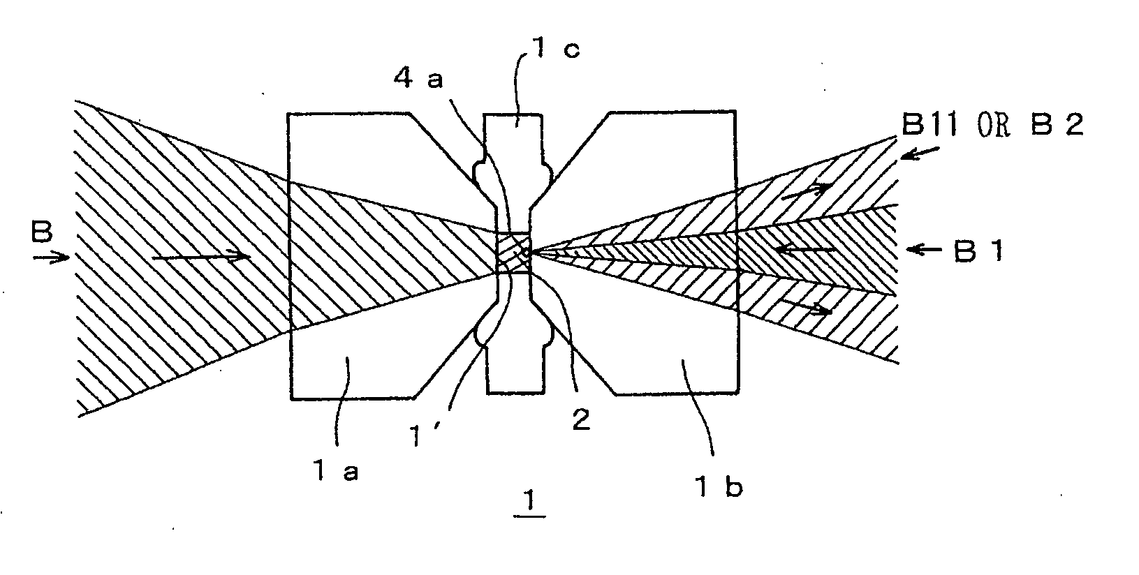
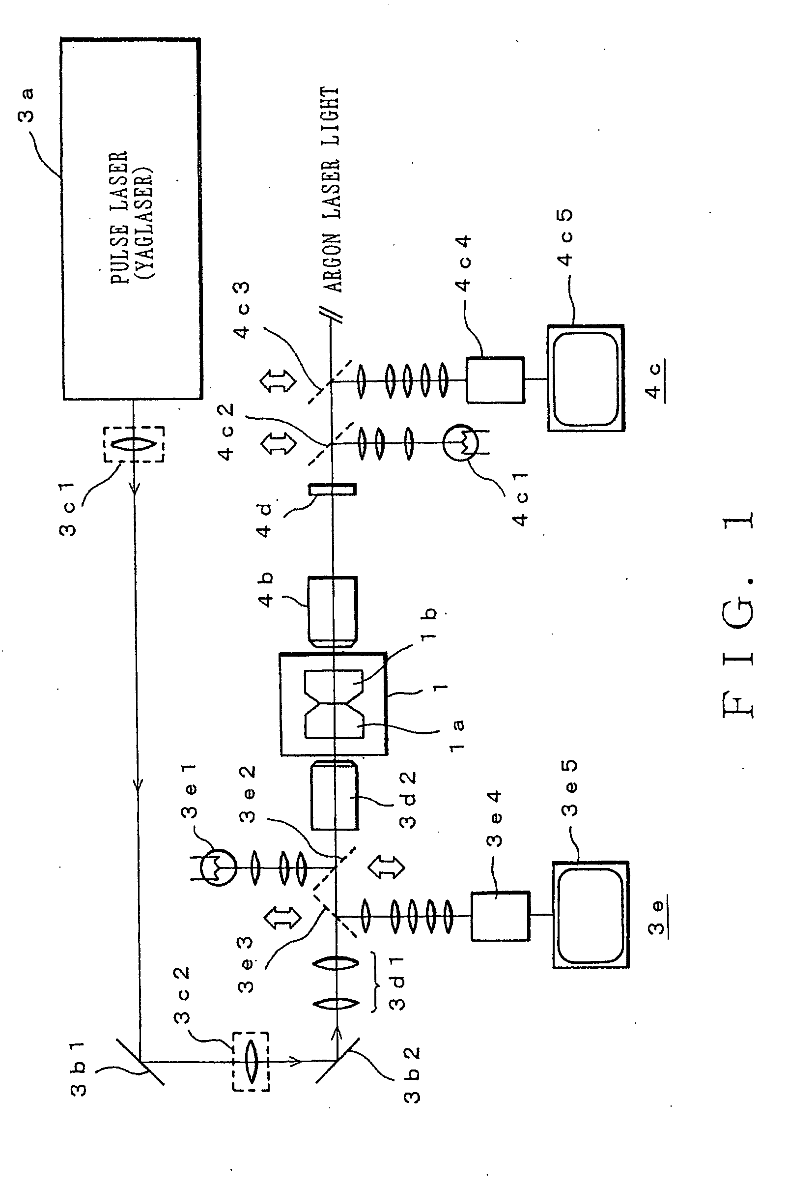
[0064]FIG. 1 is a schematic drawing showing an embodiment of the device based on the ultra-high pressure method according to the present invention. In FIG. 1, the ultra-high pressure device has a space partly surrounded by optically transparent material where a pressure source material is loaded and its atomic bonds are disrupted under volume constraint by heating the pressure source material above the boiling point thereof, and in which a high-pressure device 1 to constrain expansion of the pressure source material is installed.

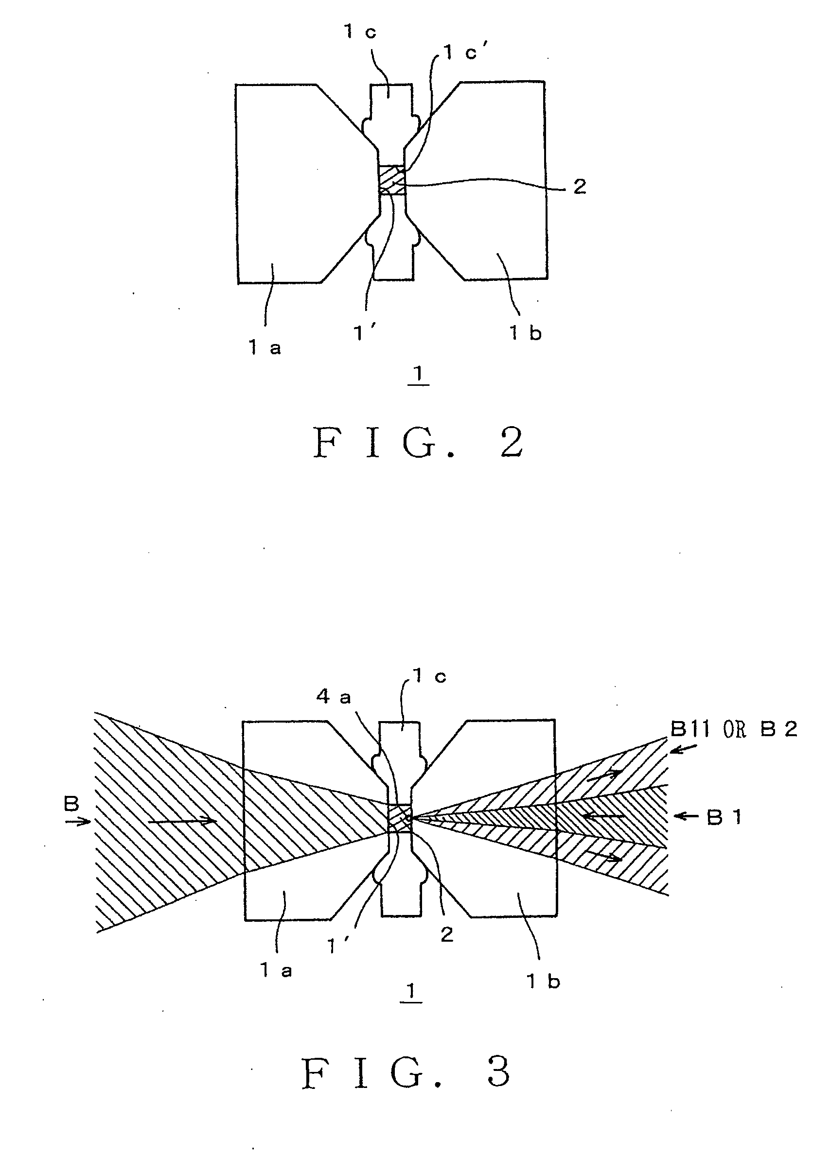
[0065] The high-pressure device 1 will be explained in detail referring to FIG. 2. As shown in FIG. 2, the high-pressure device consists of a pair of sapphire anvils 1a, 1b having high transmittance and gasket 1c having a hole which form a space 1′ where the pressure source material 2 is loaded, and a screw-clamped anvil cell (not ill...


PUM

PropertyMeasurementUnit
Pressureaaaaaaaaaa
Boiling pointaaaaaaaaaa

Abstract

A pressure source material is loaded into a space having constraint device 1, which is formed partly by optically transparent material 1a, 1b, and is disrupted under volume constraint. Light energy is externally supplied to the pressure source material constrained in the space through the optically transparent material by employing the device to apply light energy. The disruption of atomic bonds in the pressure source material is induced by heating the pressure source material above the boiling point thereof through the supplied energy. Exceptionally high pressures are generated in the space by the use of expansive forces arising from the disruption of atomic bonds. Such a configuration can implement ultrahigh pressure abilities that has not been achieved, so far.

Description

BACKGROUND OF THE INVENTION [0001] 1. Field of the Invention [0002] The present invention relates to a method and device for generating ultrahigh-pressure, and more particularly to a method and device which enables the generation of ultrahigh pressure in a space partly surrounded by an optically transparent material with supplying light energy to the space externally. [0003] 2. Description of the Related Art [0004] Although belt apparatus, multi-anvil apparatus and so on which enable the syntheses of diamond and cubic boron nitride have generally been used for the production of high pressure, high pressures above 10 GPa is difficult to achieve by using these apparatuses. The apparatuses can produce static high pressures and the sample volume can be enlarged up to 200 cm3. However, it is quite impossible to achieve high pressures in excess of 100 GPa in these apparatuses. High pressures in the 100-GPa region can be attained only with diamond anvil cells or dynamic methods. [0005] How...

Claims


Application Information

Patent Timeline
IPC IPC(8): G01J1/58B23K26/073G01N21/03
CPCB23K26/0732Y10T117/10Y10S117/904G01N21/0317
Inventor KAWASHIMA, YASUSHI
Owner TOKAI UNIV
Why Eureka
Try Eureka