
Downhole seismic source

a seismic source and downhole technology, applied in the field of subterranean borehole technology, can solve problems such as energy directed along, and achieve the effects of low energy consumption, simple and inexpensive, and large working volum

Inactive Publication Date: 2008-05-15
SCHLUMBERGER TECH CORP
View PDF18 Cites 27 Cited by
  • Summary
  • Abstract
  • Description
  • Claims
  • Application Information

AI Technical Summary

Benefits of technology

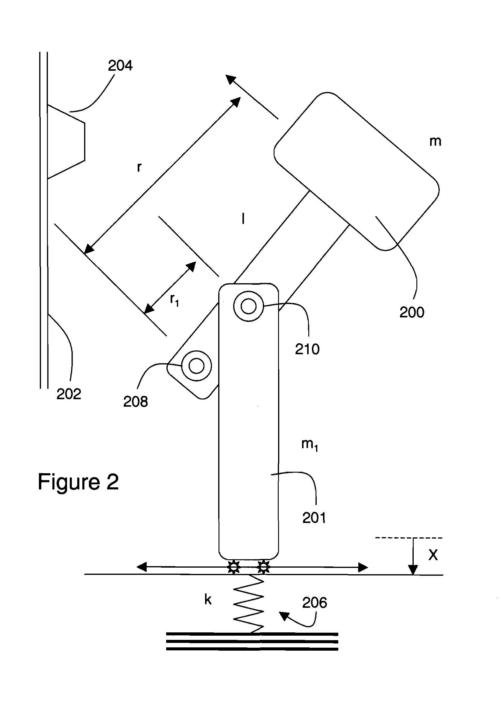
[0006]One of the advantages of the invention is that a relatively concentrated radial force is created from an axial force by virtue of the hammer rotating around the hinge. It is relatively easy to provide an axial force in the borehole environment because the available working volume in the axial direction is relatively large. Therefore, the originating force can be produced in a simple and inexpensive manner. Further, by virtue of contact occurring in a radial direction, relatively little energy is directed along undesired vectors. As a result, little energy is wasted, and most of the available energy can be directed along a vector of interest.
[0007]Other advantages of the invention are reliability and repeatability. With relatively few moving parts and simple hinges and bearings the tool is suitable for the harsh borehole environment. Because technology to accurately control the application of the axial force is readily available, the tool can be made to consistently apply a given radial impact force against the casing and borehole wall. For example, it is possible to accurately control the compression of a spring that is utilized as the source for the axial force. As a result, the strength of the elastodynamic waves will be consistent. This is useful when it is desired to observe some other variable.

Problems solved by technology

Further, by virtue of contact occurring in a radial direction, relatively little energy is directed along undesired vectors.

Method used


Image

  • Downhole seismic source
  • Downhole seismic source
  • Downhole seismic source

Examples


Embodiment Construction

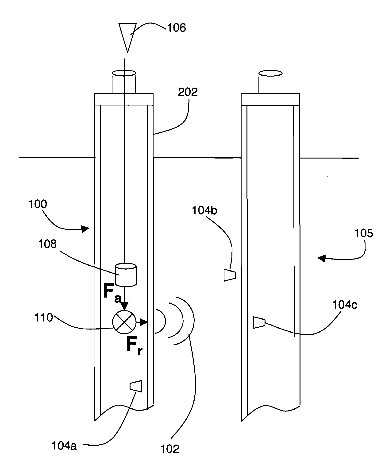
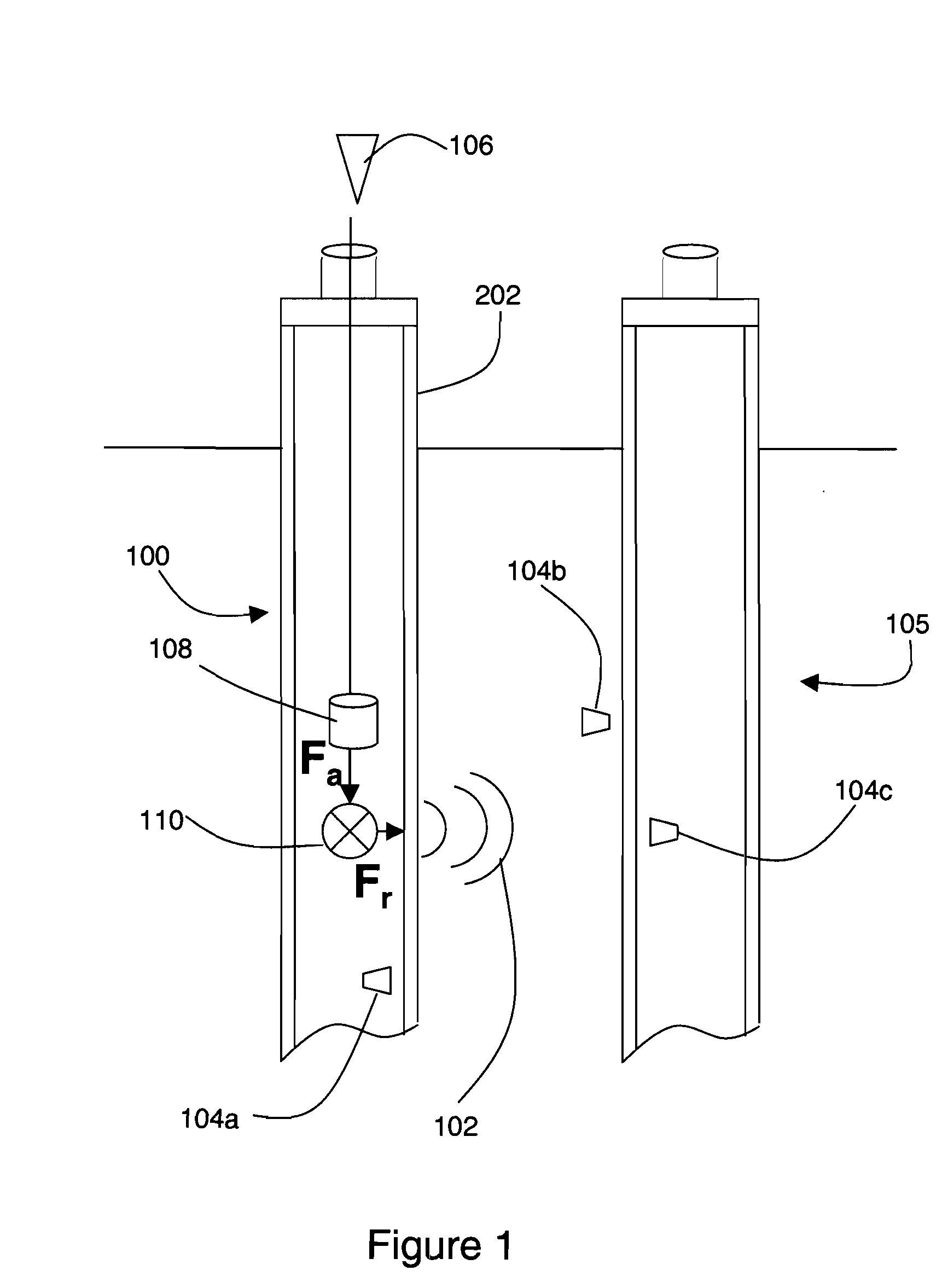
[0011]FIG. 1 illustrates a schematic representation of a downhole seismic source for facilitating data collection. The seismic source is utilized in a borehole (100) and is operable to produce elastodynamic waves (102) which can be measured by sensors (104a-104c). In particular, P, S, SH, and SV type waves can be generated. The sensors may be located within the borehole itself, e.g., sensor (104a), in a nearby borehole (105), e.g., sensor (104c), and in the formation proximate to the borehole, e.g., sensor (104b). Based on the measurements obtained by the sensors, it is possible to detect, for example, the presence of fractures, stresses, and sedimentation boundaries in the formation. Detection of such conditions can be utilized to enhance recovery of oil and gas.

[0012]The seismic source includes an energy source component (106), an energy storage component (108), and a force translator and amplification component (110). The energy source component (106) may be located either above ...


PUM


Abstract

Elastodynamic waves are generated by a tool having a hammer rotatably connected with a housing by a first hinge and an actuator arm rotatably connected with the hammer by a second hinge. An axial force applied to the actuator arm by a drive shaft and spring is translated and amplified to a radial impact force by rotation of the hammer around the first hinge. The tool may also include a stabilizer arm connected to the actuator arm by a third hinge, and connected to the housing by a fourth hinge. The housing may be an acoustic wireline tool cylinder having an opening that permits the hammer mass to extend outside the housing when rotated in a first direction. The housing may also include a second opening that permits the hammer mass to extend outside the housing when rotated in a second direction, and a third opening that permits the hammer mass to extend outside the housing when rotated between the first and second openings.

Description

FIELD OF THE INVENTION[0001]This invention relates generally to subterranean borehole technology, and more particularly to seismic analysis of formations proximate to boreholes.BACKGROUND OF THE INVENTION[0002]Seismic analysis of subterranean formations is a mature technology. Elastodynamic waves generated by a seismic source at a known location are measured with arrays of sensors. Based on the measurements, it is possible to detect, for example, the presence of fractures, stresses, and sedimentation boundaries in the formation. Preferably, the seismic source is relatively powerful because it is sometimes desirable to obtain measurements at distant sensors, and elastodynamic waves at certain frequencies are rapidly attenuated in the subterranean environment. Higher frequency elastodynamic waves are generally attenuated more rapidly than lower frequency elastodynamic waves. The seismic source should preferably be adjustable because different types of elastodynamic waves and different...

Claims


Application Information

Patent Timeline
IPC IPC(8): G01V1/147G01V1/40
CPCG01V1/147
Inventor CHANG, CHUNGCOATES, RICHARD TIMOTHYSAINT GERMAIN, JEAN G.
Owner SCHLUMBERGER TECH CORP
Learn More