
Optical signal processing apparatus, optical signal transmission system and optical signal processing method

a technology of optical signal transmission system and optical signal processing method, which is applied in the direction of electromagnetic transmission, multi-component communication, wavelength-division multiplex system, etc., can solve the problems of difficult to capture difficult to effectively estimate the influence of polarization scrambling, and difficulty in capturing a signal through clock recovery. , to achieve the effect of reducing jitter amplitude, improving jitter tolerance and facilitating efficient error correction processing

Inactive Publication Date: 2008-05-08
FUJITSU LTD
View PDF8 Cites 4 Cited by
  • Summary
  • Abstract
  • Description
  • Claims
  • Application Information

AI Technical Summary

Benefits of technology

The present invention aims to improve the efficiency of error correction processing in an optical signal transmission system by mitigating the influence of polarization mode dispersion (PMD) using polarization scrambling. The invention provides a configuration that allows for faster polarization scrambling while effectively controlling the reduction in jitter tolerance. A polarization mode dispersion compensating part is used to optically suppress differential group delay in a received optical signal, resulting in reduced jitter amplitude and improved jitter tolerance, allowing for efficient error correction processing. Overall, the invention effectively mitigates the influence of PMD in the optical fiber.

Problems solved by technology

In such a case, polarization mode dispersion, i.e., high-order polarization mode dispersion, occurs, which has complicated characteristics varying due to ambient temperature and so forth, and thus, it is not easy to estimate influence thereof to effectively compensate the same.
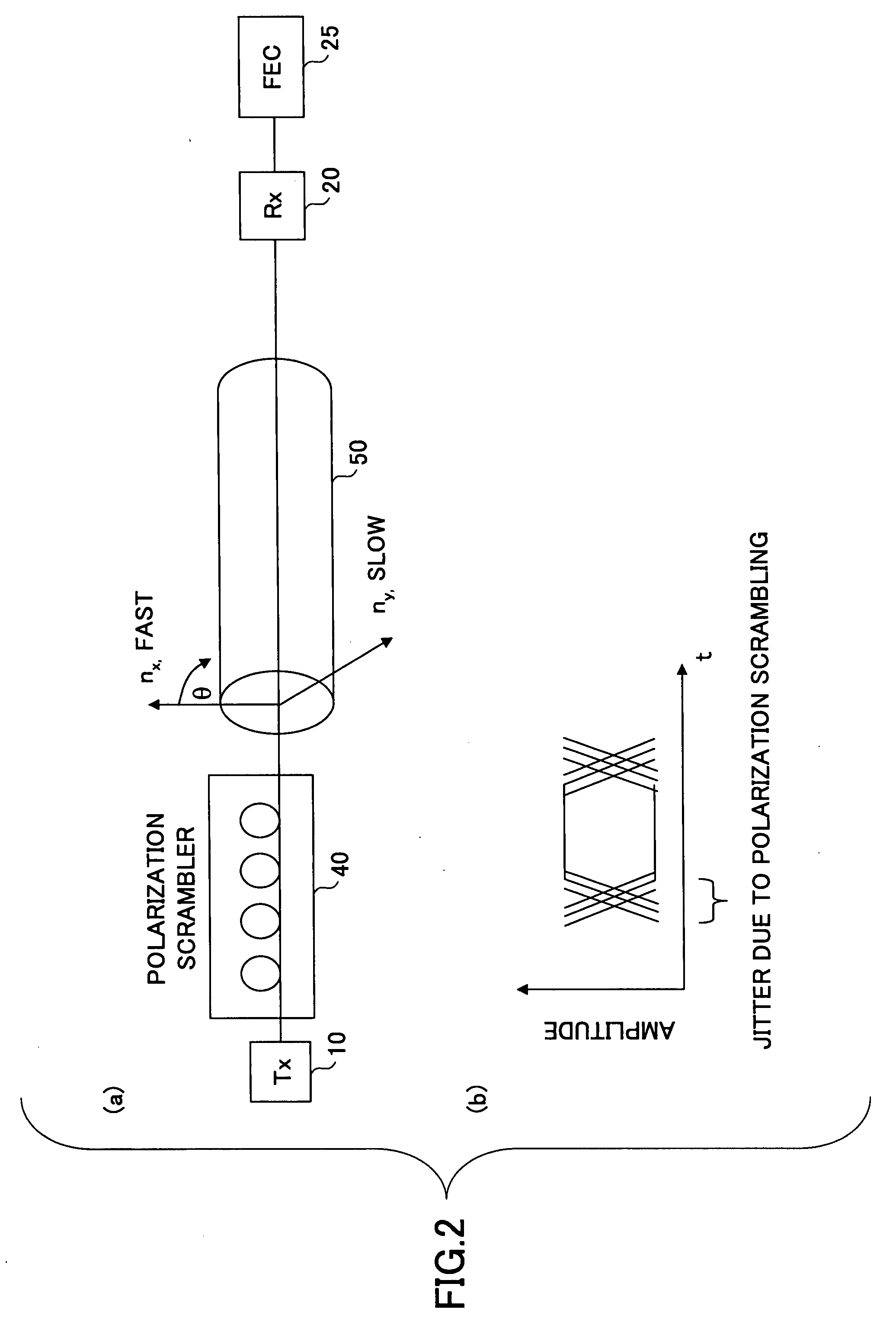
However, when the polarization scrambling is thus carried out faster, jitter caused by the polarization scrambling becomes serious accordingly as known.
As shown in FIG. 3, when a jitter frequency (horizontal axis) increases, the jitter tolerance decreases accordingly, positive capture of a signal through clock recovery becomes difficult, and thus, it is not possible to extract the transmitted signal from the received optical signal with high precision.
That is, since the jitter frequency increases as the polarization scrambling is made faster, influence of the jitter amplitude on the jitter tolerance increases, and thus, it is not possible to extract the transmitted signal from the received optical signal with high precision.
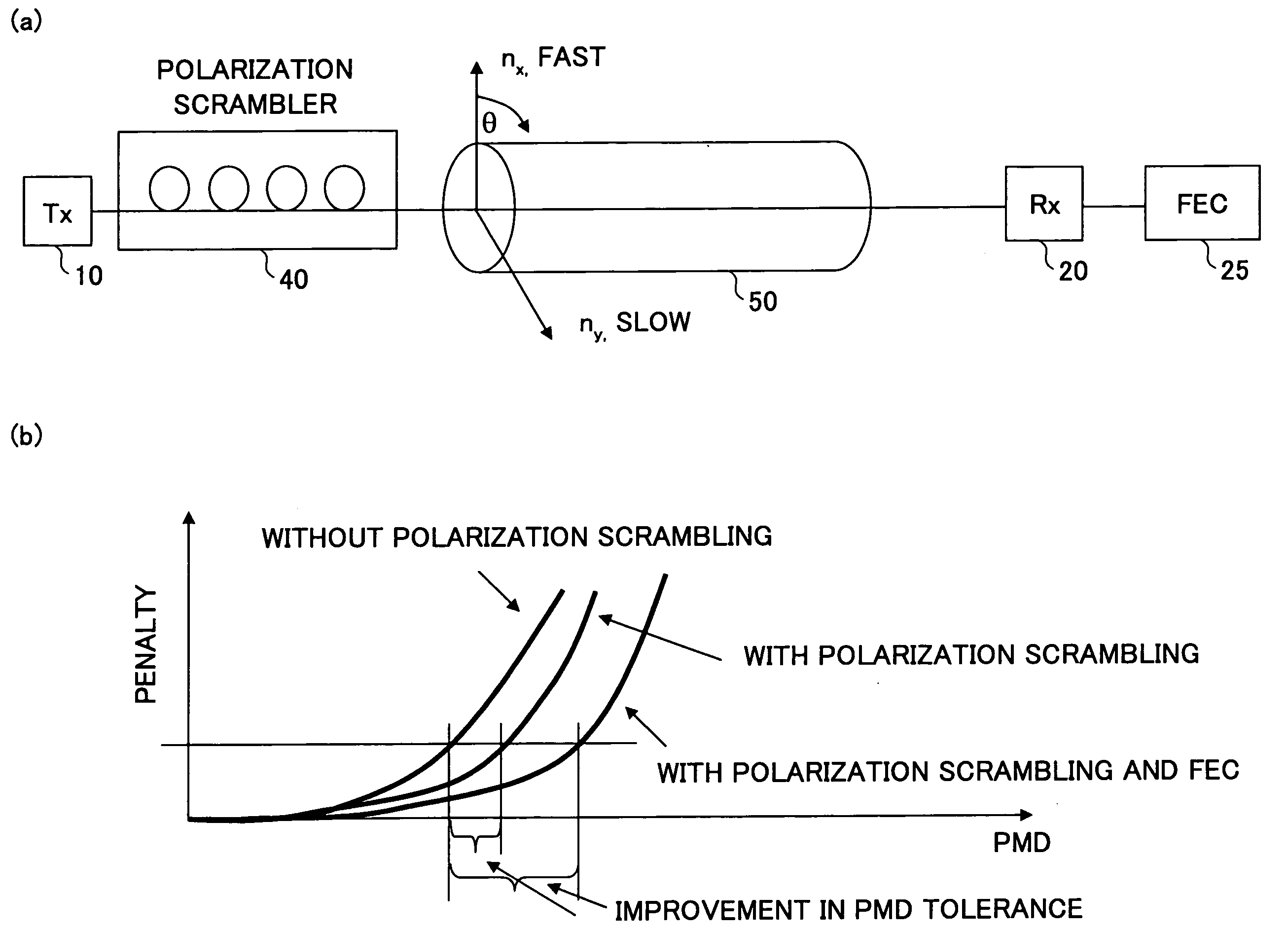
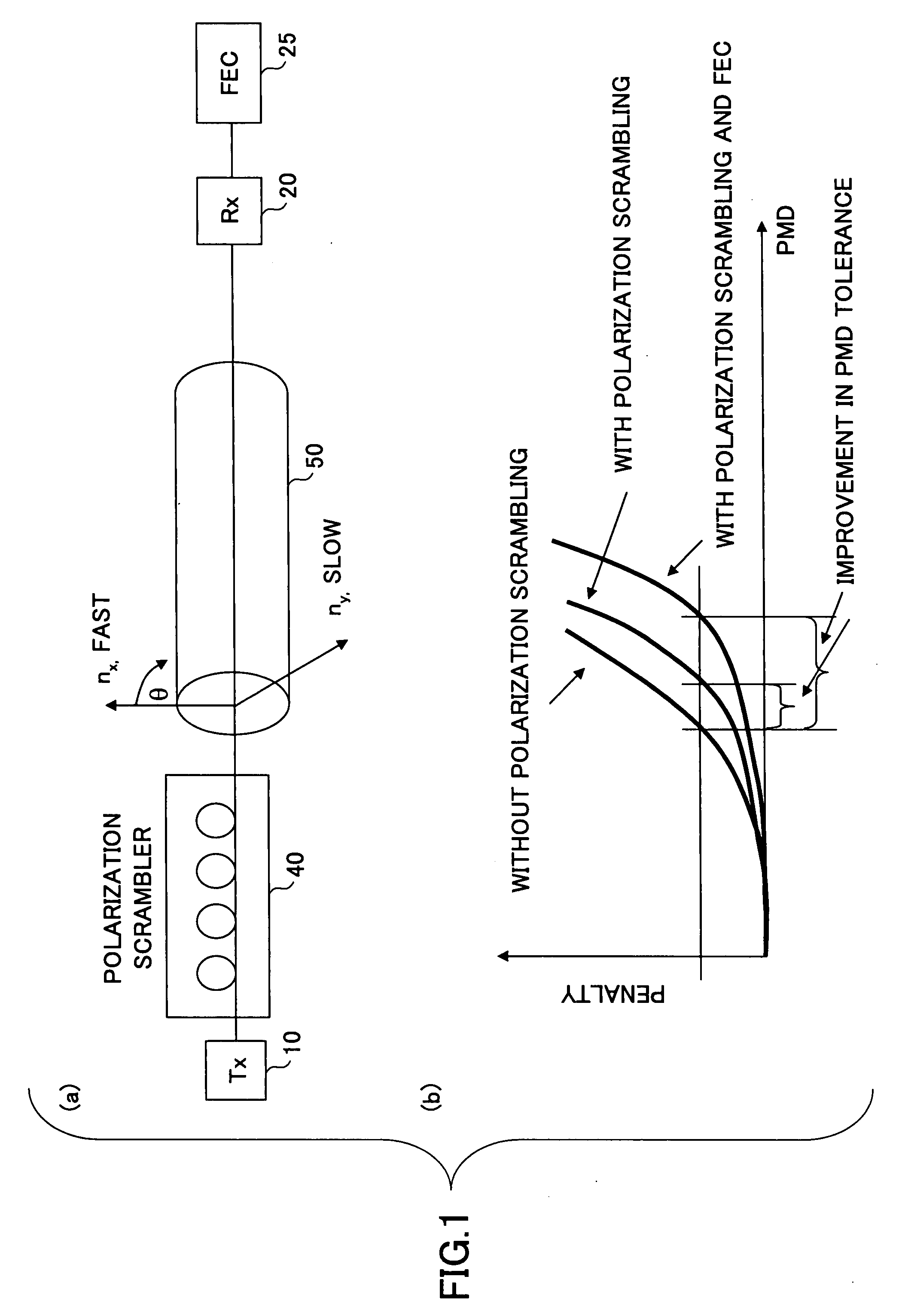
As shown in FIG. 4, when the polarization scrambling is made slower (left hand of FIG. 4), the forward error correction processing cannot be carried out efficiently, and thus, the penalty increases.
This is because, as a result of the polarization scrambling being carried out faster, influence of the jitter amplitude on the jitter tolerance increases as shown in FIG. 3, whereby clock recovery of the received signal cannot be carried out properly, and thus, it is difficult to extract the transmitted information with high precision.

Method used


Image

  • Optical signal processing apparatus, optical signal transmission system and optical signal processing method
  • Optical signal processing apparatus, optical signal transmission system and optical signal processing method
  • Optical signal processing apparatus, optical signal transmission system and optical signal processing method

Examples


second embodiment

[0056]FIG. 11 shows a block diagram illustrating an optical signal transmission system in the present invention.

first embodiment

[0057]The optical signal transmission system of FIG. 11 has a configuration the same as that of FIG. 9 described above, except a configuration and a position of an optical polarization mode dispersion compensation unit 30-0 provided in a reception station. Therefore, the same reference numerals are given to the corresponding components, and duplicate description to that of the first embodiment described above with reference to FIG. 9, will be omitted.

[0058]As shown in FIG. 11, the optical signal transmission system in the second embodiment has transmission units 10-1, 10-2, . . . , 10-n, a wavelength division multiplexer / demultiplexer 13 and a polarization scrambler 40 provided in a transmission station, an optical fiber 50 connecting between the transmission station and the reception station, the optical polarization mode dispersion compensation unit 30-0, a wavelength division multiplexer / demultiplexer 23, reception units 20-1, 20-2, . . . , 20-n and forward error correction units...


PUM


Abstract

Influence of polarization mode dispersion, occurring in an optical fiber is mitigated by means of polarization scrambling, differential group delay which a received optical signal has is optically suppressed; the optical signal in which differential group delay is thus suppressed is converted into an electric signal; and error correcting processing is carried out on the electric signal obtained, a jitter amplitude in the received optical signal is suppressed, influence of which to a jitter tolerance increases due to increase in speed of the polarization scrambling.

Description

BACKGROUND OF THE INVENTION[0001]1. Field of the Invention[0002]The present invention relates to an optical signal processing apparatus, an optical signal transmission system and an optical signal processing method, and, in particular, to an optical signal processing apparatus and an optical signal processing method applied to an optical signal transmission system in which influence of polarization mode dispersion of an optical fiber is mitigated by means of polarization scrambling, and the optical signal transmission system.[0003]2. Description of the Related Art[0004]Technology of mitigating influence of polarization mode dispersion (PMD) of an optical fiber which is a signal transmission medium for transmitting an optical signal, by polarization scrambling, is known (see the non-patent documents 1-4, mentioned below).[0005]FIG. 1 (a) shows a block diagram illustrating an optical signal transmission system in such case.[0006]In FIG. 1 (a), an optical signal transmitted from a tran...

Claims


Application Information

Patent Timeline
Patent Type & Authority Applications(United States)
IPC IPC(8): H04B10/02H04B10/07H04B10/2507H04B10/2569H04J14/00H04J14/02
CPCH04B10/532H04B10/2569
Inventor RASMUSSEN, JENSISOMURA, AKIHIKO
Owner FUJITSU LTD
Learn More