
Bandwidth calibration of active filter

a filter and bandwidth technology, applied in the field of active filters, can solve the problems of bias diodes offset much of the temperature sensitivity of the ota's transconductance, extra semiconductor/chip area and power consumption, and achieve the effect of low gain bandwidth, low or, reduce, the power consumption of the filter

Inactive Publication Date: 2008-05-01
ST ERICSSON SA
View PDF4 Cites 9 Cited by
  • Summary
  • Abstract
  • Description
  • Claims
  • Application Information

AI Technical Summary

Benefits of technology

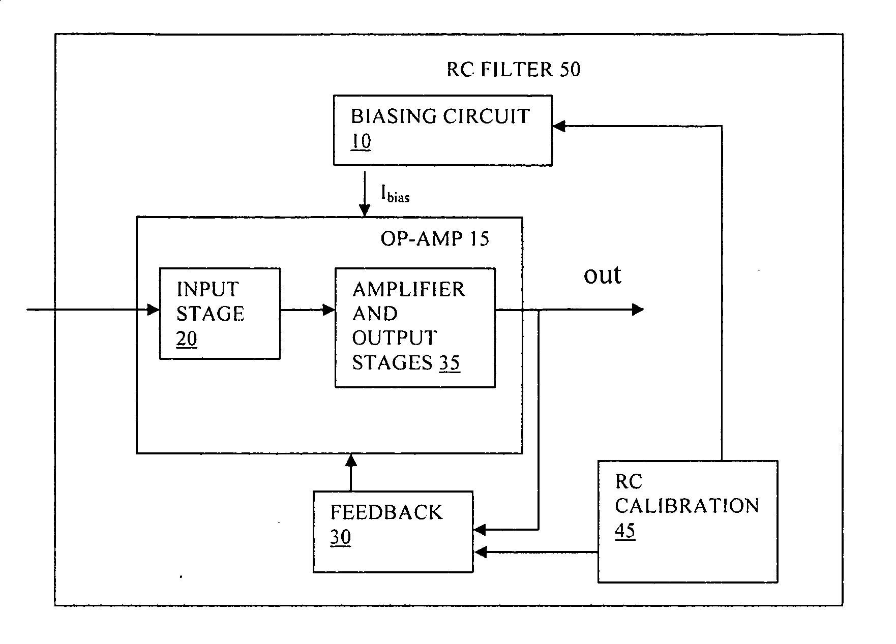
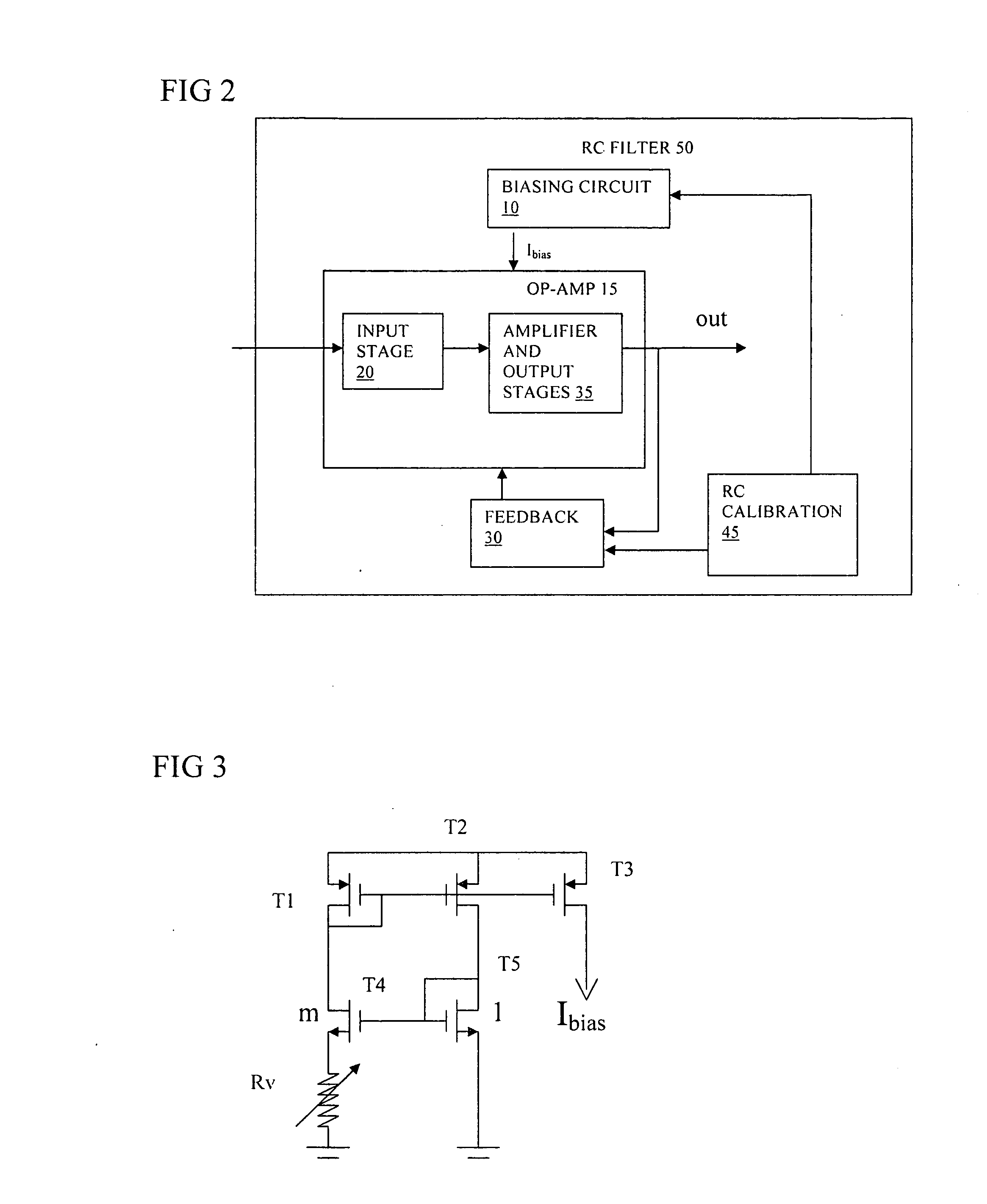
[0006]An object of the invention is to provide improved active filters, methods of calibration, and corresponding software and integrated circuits. An advantage of the present invention is to reduce pole frequency variation in an active filter, e.g. an RC filter, between devices. One aspect of the invention calibrates the gain bandwidth of the op-amp either with existing calibration circuits or with a further calibration circuit. Hence one aspect of the present invention is to control the bandwidth of an active filter. For example, a biasing circuit is used to fix the gain bandwidth product, which reduces variations on the filter pole frequency. The following is done: In the RC-calibration circuitry, the capacitance value is (digitally) changed to calibrate the product (R)(C). These calibration bits are used to change the capacitance values in the filter so as to keep there also the product (R)(C) constant.
[0007]In one aspect of the present invention, use is made of the same adjustment or calibration information, e.g. a number of bits, to alter a resistor in biasing circuitry of an amplifier, e.g. an opamp, to keep the GBW (=Gm / C) of the amplifier, e.g. opamp, constant, which benefits, therefore, the filter design.
[0008]This provides the advantage of a lower gain bandwidth without the need to provide safety margins to allow for manufacturing and other tolerances. At least some of these advantages can be obtained without requiring additional calibration circuitry. Another advantage of embodiments of the present invention is to have a low, or to reduce, power consumption of the filter, e.g. current consumption. This can be achieved by reusing values obtained from an existing calibration circuit in a circuit for calibrating the gain bandwidth. According to an aspect, the invention provides:
[0009]An active filter having an input stage having an amplifier such as an operational amplifier and a biasing circuit arranged to bias the input stage, e.g. the amplifier to set and / or maintain a gain bandwidth product of the input stage, e.g. the amplifier, to obtain a desired pole frequency of the filter.
[0010]This can help to set the pole frequency more accurately and can thus reduce the need for bandwidth margin to be provided to allow, for example, for manufacturing process variations in gain-bandwidth product.
[0011]The present invention also provides a method of calibrating an active filter having an input stage having an amplifier such as an operational amplifier and a biasing circuit arranged to bias the input stage, e.g. the amplifier, the method comprising setting and / or maintaining a gain bandwidth product of the input stage, e.g. of the amplifier, to obtain a desired pole frequency of the filter or to obtain a pole frequency within a desired range.

Problems solved by technology

Firstly, when used with input resistors, the diodes distort the differential input voltage to offset a significant amount of input stage non linearity at higher differential input voltages.
Secondly, the action of the biased diodes offsets much of the temperature sensitivity of the OTA's transconductance.
However not all effects are compensated so that it is known to provide a margin of error in the system having the filter.
Providing a margin of safety can result in extra semiconductor / chip area and power consumption.
For example, the gain bandwidth of the op-amp can be made so large that there is little effect on the filter pole (so that variations do not matter) but this results in higher current consumption.

Method used


Image

  • Bandwidth calibration of active filter
  • Bandwidth calibration of active filter
  • Bandwidth calibration of active filter

Examples


Embodiment Construction

[0034]The present invention will be described with respect to particular embodiments and with reference to certain drawings but the invention is not limited thereto, but only by the claims. The drawings described are only schematic and are non-limiting. In the drawings, the size of some of the elements may be exaggerated and not drawn on scale for illustrative purposes. Where the term “comprising” is used in the present description and claims, it does not exclude other elements or steps. Where an indefinite or definite article is used when referring to a singular noun e.g. “a” or “an”, “the”, this includes a plural of that noun unless something else is specifically stated.

[0035]The term “comprising”, used in the claims, should not be interpreted as being restricted to the means listed thereafter; it does not exclude other elements or steps. Thus, the scope of the expression “a device comprising means A and B” should not be limited to devices consisting only of components A and B. It...


PUM


Abstract

An active RC filter has an op-amp and a biasing circuit arranged to bias the op-amp to set a gain bandwidth product of the op-amp according to a desired pole frequency of the filter. The biasing circuit is operable according to an output of an RC calibration circuit. The op-amp can be an OTA transconductance amplifier, and the biasing circuit can be arranged to maintain a constant product of R and transconductance at an input of the transconductance amplifier. This biasing can help to set the pole frequency more accurately and can thus reduce the need for bandwidth margin to be provided to allow for manufacturing process variations.

Description

BACKGROUND OF THE INVENTION[0001]1. Field of the Invention[0002]This invention relates to active filters, to methods of calibration, and to corresponding software and integrated circuits.[0003]2. Discussion of the Related Art[0004]It is known to provide active filters using op-amps (operational amplifiers) with feedback. In general such a filter is illustrated in FIG. 1a in a negative feedback arrangement. This shows an op-amp, an input resistor R2, and a feedback resistor R1 coupled from the op-amp output to the op-amp negative input. Typically R1=R2 and both have a resistance value R, but other arrangements are possible. A capacitor C1 is coupled in parallel with the feedback resistor. It is known to use OTAs (Operational transconductance amplifiers) in such filters. The OTA is a voltage-controlled current source whereas a conventional op-amp is a voltage-controlled voltage source. The OTA is similar to a standard op-amp in that it has a high impedance differential input stage and...

Claims


Application Information

Patent Timeline
IPC IPC(8): H03K5/00
CPCH03F1/08H03F3/45475H03F2200/264H03H11/1291H03F2203/45138H03F2203/45526H03F2203/45048H03H2210/023H03H2210/04
Inventor TERRYN, STEVENJOOS, DIETER
Owner ST ERICSSON SA
Learn More