
Method of manufacturing an ink-jet recording head

a technology of inkjet recording head and manufacturing method, which is applied in the direction of recording equipment, recording information storage, instruments, etc., can solve the problems of inability to achieve accurate control limit the improvement of the inability to accurately control the depth of the ink inlet passage, etc., to achieve the effect of high accuracy, low cost and low production cos

Inactive Publication Date: 2008-04-03
SEIKO EPSON CORP
View PDF8 Cites 2 Cited by
  • Summary
  • Abstract
  • Description
  • Claims
  • Application Information

AI Technical Summary

Benefits of technology

The present invention provides an ink-jet recording head with a very small unevenness in ink jetting characteristics of nozzle holes, and a method of manufacturing such an ink-jet recording head. The invention also provides an ink-jet recording head with improved accuracy and dot density, and a method of manufacturing such an ink-jet recording head. The invention also provides an ink-jet recording head that can be formed in very small dimensions and increased level of integration. The invention solves the problem of unevenness in ink jetting characteristics by providing a plate-shaped member with an elastic and deformable portion surrounding the land, which is capable of being elastically deformed by a deformation of the pressure producing device. The invention also provides an ink-jet recording head with improved accuracy and dot density by using a stainless steel plate-shaped member with a partition wall and a land formed by etching a desired portion of the plate-shaped member. The invention also provides an ink-jet recording head with an auxiliary ink storage chamber communicated with the common ink storage chamber.

Problems solved by technology

Consequently, pressure cannot be properly applied to the pressure chambers.
It is difficult to achieve the accurate control of the depth of the ink inlet passages 310 by such a method and there is a limit to the improvement of the accuracy of the depth of the ink inlet passages 310.
The electroformed plate needs an additional process for removing the electroformed plate from the pattern, which is one of factors of cost increases.
Therefore it is difficult to form the passages accurately in a desired depth, which is a restriction on accuracy improvement.
The electroformed plates needs an additional process for removing the electroformed plate from the pattern, which is one of factors of cost increases.

Method used


Image

  • Method of manufacturing an ink-jet recording head
  • Method of manufacturing an ink-jet recording head
  • Method of manufacturing an ink-jet recording head

Examples


first embodiment

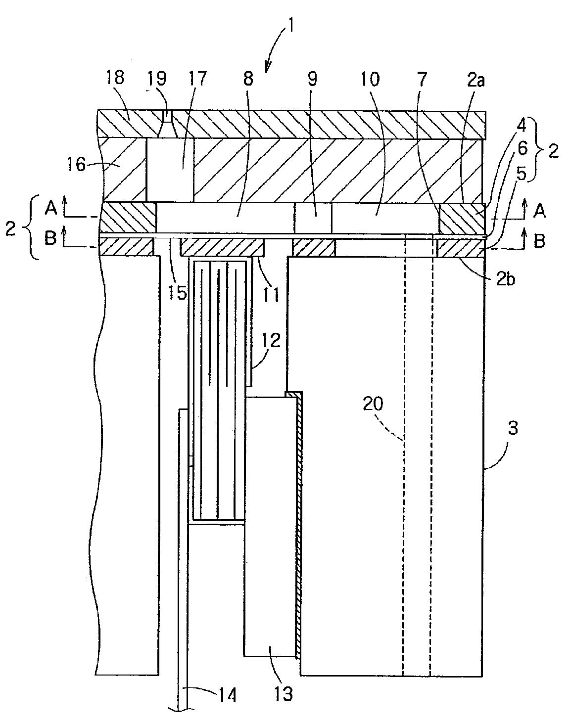
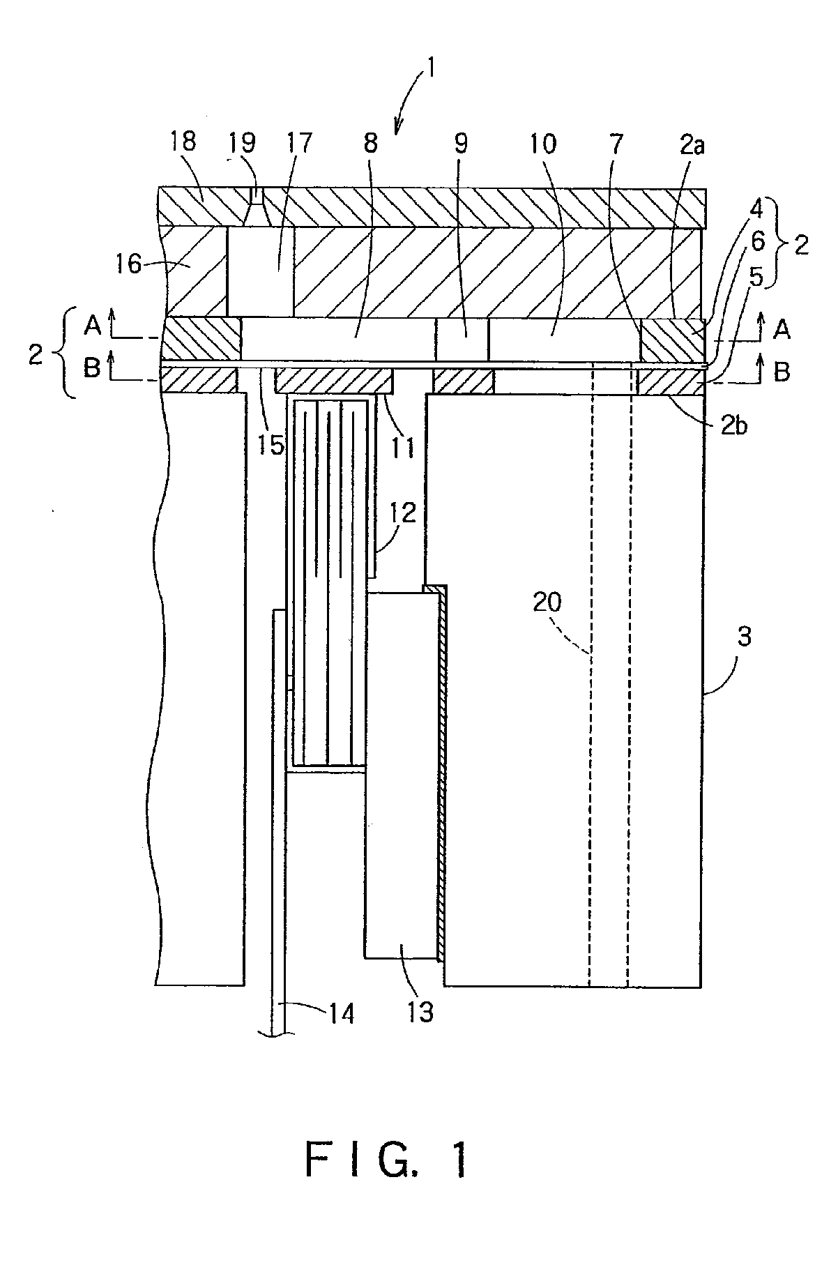
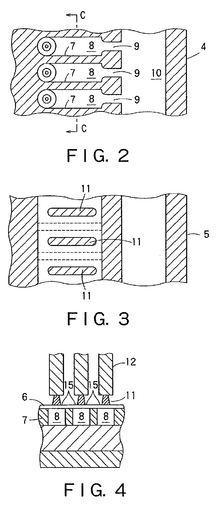
[0141] A method of manufacturing the ink-jet recording head in the first embodiment will be described hereinafter. The plate-shaped member 2 is formed by sandwiching the intermediate layer 6 between the first layer 4 and the second layer 5. The plate-shaped member 2 may be any one of those shown in FIGS. 5A, 5B and 5C. The plate-shaped member 2 shown in FIG. 5A has an intermediate layer 6 formed of a polyimide resin (PI), and a first layer 4 and a second layer 5 formed of a stainless steel. The intermediate layer 6 may be formed of titanium. Various materials may be used in proper combinations for forming the first layer 4, the second layer and the intermediate layer 6. Essentially, a combination of materials is determined selectively so that the first layer 4 and the second layer 5 can be etched selectively over the intermediate layer 6.

[0142] The plate-shaped member 2 shown in FIG. 5B has an intermediate layer 6 formed of a polymeric material, such as PPS, and a first layer 4 and ...

sixth embodiment

[0175] A passage unit included in an ink-jet recording head in a sixth embodiment according to the present invention will be described with reference to FIGS. 12A and 12B, in which parts like or corresponding to those of the ink-jet recording head shown in FIGS. 11A, 11B and 11C are denoted by the same reference characters and the description thereof will be omitted. This ink-jet recording head employs piezoelectric vibrators 106A of a flexural vibration mode. A vibrating unit formed by sandwiching the piezoelectric vibrator 106A between an upper electrode 116 and a lower electrode 117 is attached to the vibrating plate 105 included in the passage unit 101.

[0176] The piezoelectric vibrators 106A are driven for flexural vibrations by driving signals to change the pressure in the pressure chambers 107 to jet ink particles through the nozzle holes 108. The ink-jet recording head in the sixth embodiment is the same in operation and effect as that in the fifth embodiment shown in FIGS. 1...

seventh embodiment

[0183]FIG. 14 shows an ink-jet recording head in a seventh embodiment according to the present invention, which is similar to the ink-jet recording head shown in FIGS. 11A, 11B and 11C and hence parts like or corresponding to those of the ink-jet recording head shown in FIGS. 11A, 11B and 11C are denoted by the same reference characters and the description thereof will be omitted.

[0184] As shown in FIG. 14, the first base plate 120 is provided with the connecting holes 121 and auxiliary ink storage chambers 109A formed by etching. The auxiliary ink storage chambers 109A are additional ink storage chambers aligned with the ink storage chambers 109 formed in the second base plate 122.

[0185] Thus, the ink-jet recording head in the seventh embodiment is provided additionally with the auxiliary ink storage chambers 109A for the effective use of space. The ink storage chambers 109 and the auxiliary ink storage chambers 109A provide a sufficiently large ink storage volume, reduce passage ...


PUM

PropertyMeasurementUnit
pressureaaaaaaaaaa
thicknessaaaaaaaaaa
widthaaaaaaaaaa

Abstract

An ink-jet recording head has a plate-shaped member including a first layer with a partition wall formed by a first etching process and defining a pressure chamber, an ink inlet passage and a common ink storage chamber, a second layer with a land formed by a second etching process so as to correspond to the pressure chamber, and an intermediate layer sandwiched between the first and the second layers. The recording head also has a pressure producing device disposed with its extremity in contact with the land, and a nozzle plate with a nozzle hole bonded to the front surface of the plate-shaped member. An ink particle is jetted through the nozzle hole when the pressure in the pressure chamber is changed by the pressure producing device.

Description

CROSS-REFERENCE TO RELATED APPLICATIONS [0001] This is a divisional of application Ser. No. 10 / 786,331 filed Feb. 26, 2004. Application Ser. No. 10 / 786,331 is a divisional of application Ser. No. 09 / 708,514, filed Nov. 9, 2000. Priority is claimed from JP 2000-290507 filed Sep. 25, 2000, from JP 2000-19135 filed Jan. 27, 2000, from JP 1999-328458 filed Nov. 18, 1999, and also from JP 1999-321328 filed Nov. 11, 1999. The entire disclosures of the prior applications, application Ser. No. 10 / 786,331 and 09 / 708,514, and the above-identified priority documents, are hereby incorporated by reference.BACKGROUND OF THE INVENTION [0002] 1. Field of the Invention [0003] The present invention relates to an ink-jet recording head and a method of manufacturing the same. More particularly, the present invention relates to an ink-jet recording head that jets ink particles through nozzle holes by changing the pressure of pressure chambers by deformations of pressure producing devices and a method of...

Claims


Application Information

Patent Timeline
Patent Type & Authority Applications(United States)
IPC IPC(8): G11B5/127B41J2/045B41J2/055B41J2/14B41J2/16
CPCB41J2/14274B41J2/1612B41J2/1623B41J2/1626B41J2/1631Y10T29/42B41J2002/14362B41J2002/14419Y10T29/49401Y10T29/494B41J2/1632
Inventor KITAHARA, TSUYOSHI
Owner SEIKO EPSON CORP
Learn More