
Electrical connector for medical device

a technology of electrical connectors and medical devices, applied in the direction of guide wires, sensors, medical science, etc., can solve the problems of still prevailing short circuit risk, and achieve the effect of minimizing the risk of significant and undesired decrease in electrical resistan

Inactive Publication Date: 2008-03-27
RADI MEDICAL SYST
View PDF7 Cites 27 Cited by
  • Summary
  • Abstract
  • Description
  • Claims
  • Application Information

AI Technical Summary

Benefits of technology

"The patent text describes an improved male connector for a sensor guide wire that reduces the risk of short circuits and contamination. The connector has conductive members that are insulated from each other and from the surrounding material using a hydrophobic material. This prevents bodily fluids and other contaminants from forming a conductive path that could cause a short circuit. The sensor guide wire can also have a jacket and a distal coil, and the sensor element is protected from the surrounding medium. Overall, this invention ensures proper functioning and reliability of the sensor guide wire."

Problems solved by technology

Although a wiper device reduces the contamination problem, the risk of a short circuit still prevails, in particular if the male and female connectors are repeatedly disconnected and reconnected.

Method used


Image

  • Electrical connector for medical device
  • Electrical connector for medical device
  • Electrical connector for medical device

Examples


Embodiment Construction

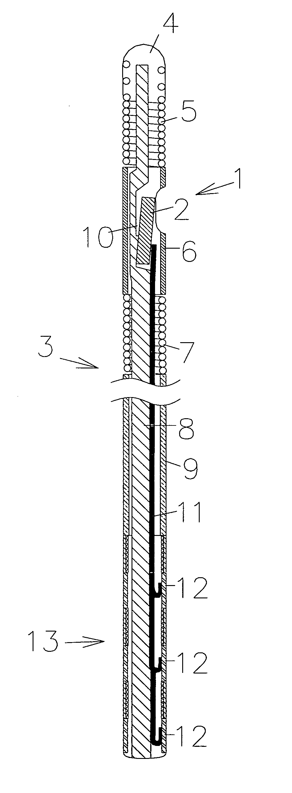
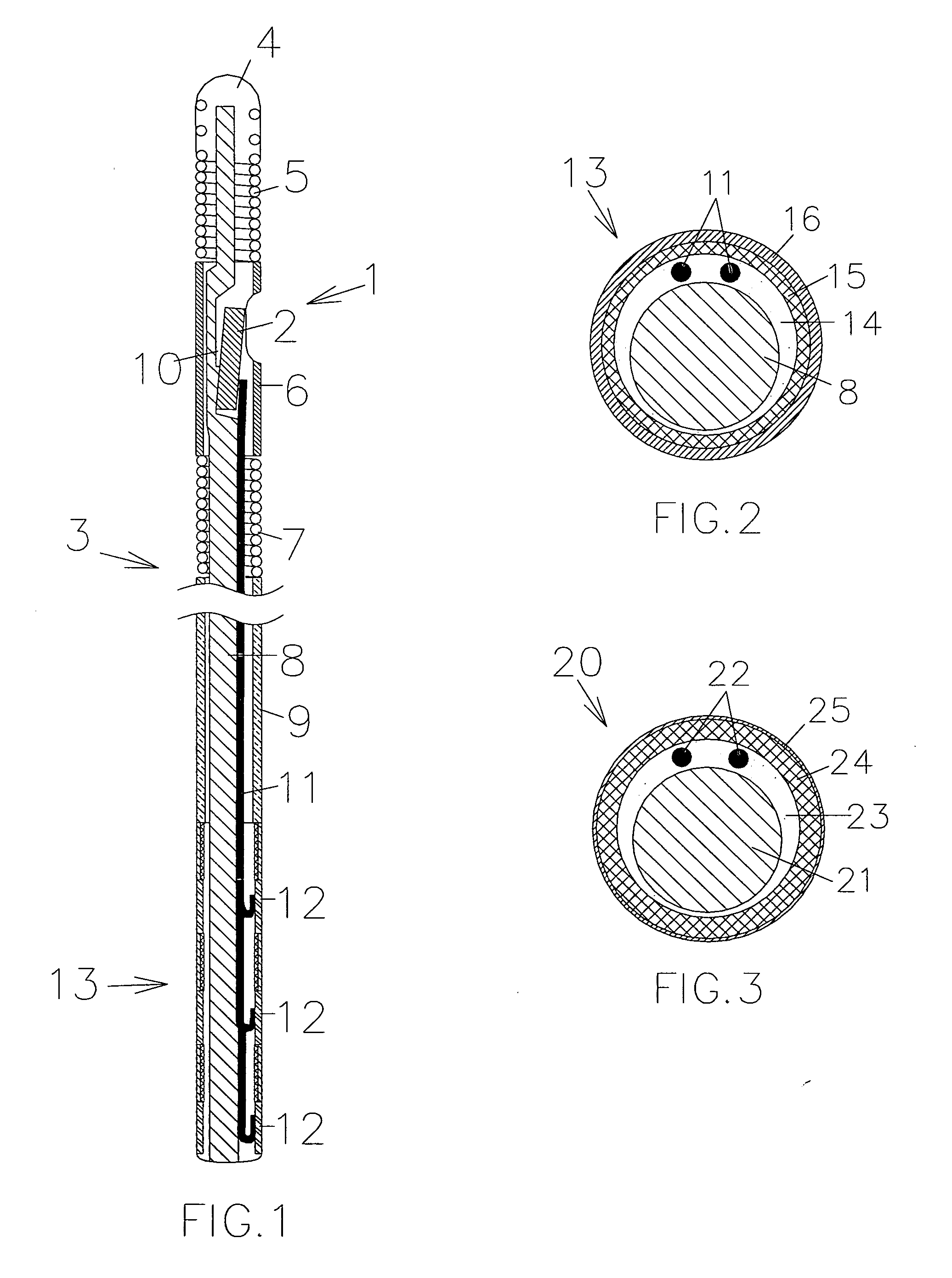
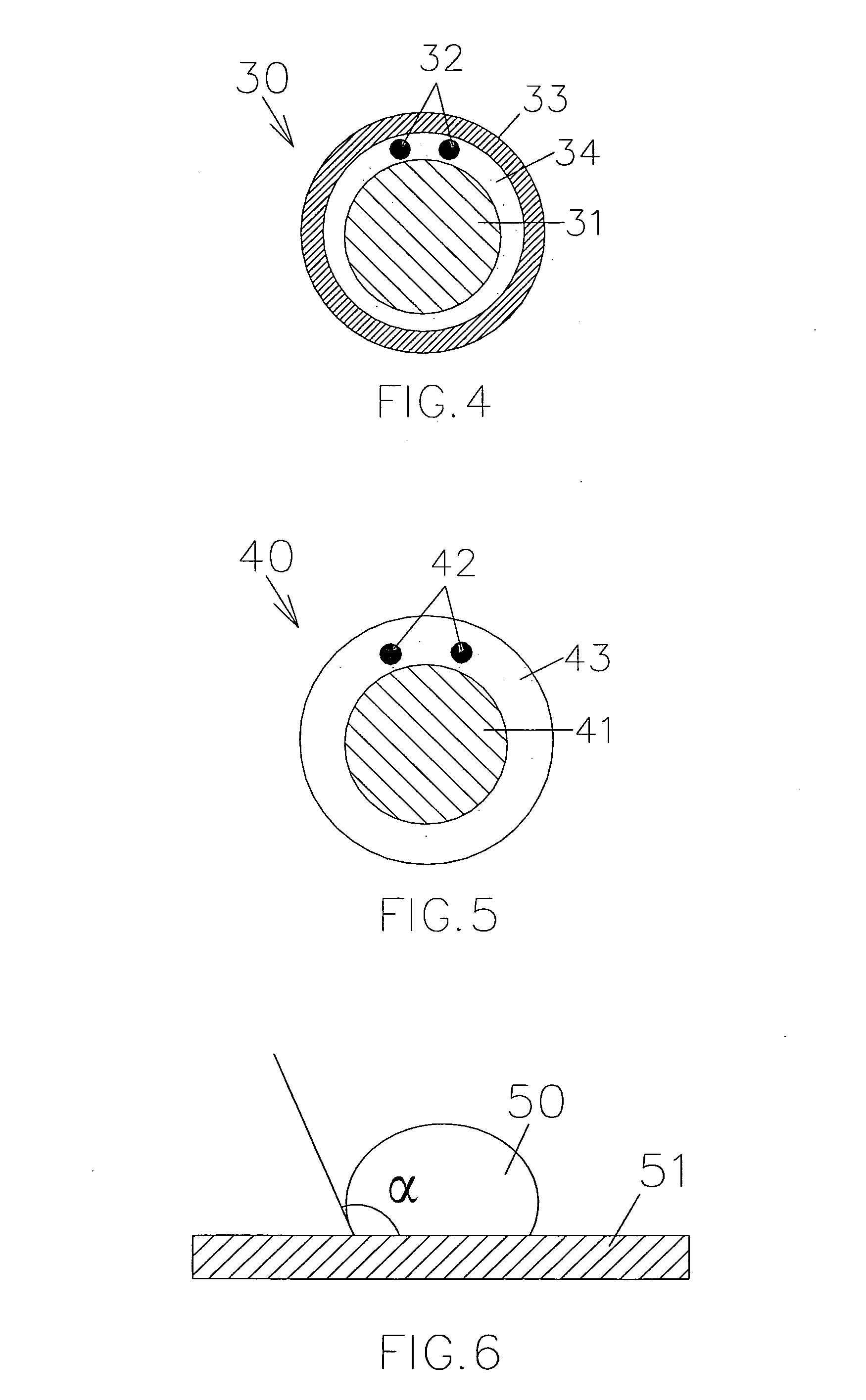
[0017]FIG. 1 illustrates schematically the general design of a sensor and guide wire assembly 1 according to a first embodiment of the present invention. The sensor and guide wire assembly 1 comprises a sensor element 2, which is arranged in a distal portion of a sensor guide wire 3. More specifically, the sensor guide wire 3 comprises a distal tip 4, a distal coil spring 5, a jacket or sleeve 6, a proximal coil spring 7, a core wire 8, and a proximal tube 9. The distal coil spring 5 is attached to the distal tip 4 and extends to the jacket 6, which serves as a housing for the sensor element 2. The proximal coil spring 7 extends between the jacket 6 and the proximal tube 9. The sensor element 2 is mounted in a recess 10 in a distal portion of the core wire 8, and is through a window in the jacket 6 in fluid communication with the medium, e.g. blood, surrounding the sensor and guide wire assembly 1. The sensor and guide wire assembly 1 comprises further a number of signal transmittin...


PUM


Abstract

A male connector (13; 20; 30; 40) for a sensor and guide wire assembly (1) for intravascular measurements of a physiological variable in a living body comprises a number of conductive members (12) separated by insulating materials (14, 15, 16; 23, 24, 25; 33, 34; 43). According to the invention, the insulating material has a hydrophobic outer surface (16; 25; 33; 43) to prevent electrically conductive contaminations from forming a superficial, electrically conductive path between two neighbouring conductive members.

Description

FIELD OF THE INVENTION[0001]The invention relates generally to sensors mounted on guide wires for intravascular measurements of physiological variables in a living body, and in particular to the design of the connector part of such sensor guide wires.BACKGROUND OF THE INVENTION[0002]Sensor and guide wire assemblies in which a sensor, adapted for measurements of physiological variables in a living body, such as blood pressure and temperature, is mounted at a distal portion of a guide wire are known.[0003]For example, the U.S. Pat. No. Re. 35,648, which is assigned to the present assignee, discloses a sensor and guide wire assembly comprising a sensor element, an electronic unit, signal transmitting cables connecting the sensor element to the electronic unit, a flexible tube having the signal cables and the sensor element disposed therein, a solid metal wire, and a coil attached to the distal end of the solid wire. The sensor element comprises a pressure sensitive device, e.g. a membr...

Claims


Application Information

Patent Timeline
Patent Type & Authority Applications(United States)
IPC IPC(8): A61M25/00
CPCA61B5/0215A61B5/6851A61M25/09A61M2205/3327A61M2025/09175A61M2025/09183A61M2025/09133
Inventor VON MALMBORG, PARGUSTAFSSON, PAR
Owner RADI MEDICAL SYST
Learn More