
Non-pneumatic tire

a technology of non-pneumatic tires and tyres, which is applied in the field of non-pneumatic tires, can solve the problems of decreased and even lost filled air pressure, and achieve the effects of selective enhancement of longitudinal stiffness, convenient provision of vertical, longitudinal and lateral stiffness, and selective increase of lateral stiffness of tires

Inactive Publication Date: 2008-03-27
BRIDGESTONE CORP
View PDF11 Cites 33 Cited by
  • Summary
  • Abstract
  • Description
  • Claims
  • Application Information

AI Technical Summary

Benefits of technology

[0014]According to the first aspect of the non-pneumatic tire of the present invention, one ore more kinds of elastic means imparting a required stiffness against relative displacements in the radian, circumferential and width directions with respect to the rim and ring members is provided on the link mechanisms consisting of the pair of link members which are aligned, for example, in the meridian direction and which connect the rim member with the ring member on which the tread is formed. This can eliminate a necessity of filling an air pressure or any other internal pressure into the tire provided with a tread on the circumferential face of the ring member, and can easily provide vertical, longitudinal and lateral stiffnesses of required magnitudes to the tire on the basis of a pre-selected elastic force and according to the amount of the displacement from the neutral position, with the stiffnesses being independent with each other.
[0015]When one of the elastic means consists of a spring member which connects respective hinge connections of the second ends of the links of the pair of link members with each other and which has a natural length under a unloaded condition, the various required stiffnesses can be effectively exerted by the spring member.
[0016]That is, under an action of a vertical load on the tire, a compressive or tensile reactive force is produced on the spring member by a displacement of the link member in the compressive direction in the grounding surface side of the tire tread due to a displacement of the ring member approaching to the rim member, so that a required vertical stiffness can be exerted on the tire. On the other hand, under an action of a longitudinal load on the tire, a tensile or compressive reactive force is produced on the spring member by a relative displacement of the link member in the elongation direction in the grounding surface side due to a relative displacement of the ring member in a leading or lagging phase with respect to the rim member, so that a required longitudinal stiffness can be exerted on the tire. Further, under a lateral load on the tire, a tensile or compressive reactive force is produced on the spring member by an increase of the distance between the pair of link members and the hinge connection due to a relative displacement of the ring member in the width direction of the rim member, so that a required lateral stiffness can be exerted on the tire.
[0017]In such a tire, when another one of the elastic means consisting of a torsion spring member such as a torsion spring or a rubber bushing which is arranged at the connection of the first end of at least one of the link of the link members and which imparts a stiffness against swing displacements of the link in the circumferential direction is provided in addition to the above-mentioned spring means, the longitudinal stiffness of the tire can be selectively enhanced under an action of the torsion spring member.
[0018]Moreover, when there is provided a further elastic means consisting of a torsion bar disposed between the hinge connection of the second ends of the links of the pair of link members via a pair of connecting rods having moment arms, the lateral stiffness of the tire can be selectively increased by a torsional force applied to the torsion bar via the moment arm due to a mutual change of the radial position of the above-mentioned hinge connection or, in other words, the radial height of the hinge connection from the rim member on the occasion of a relative displacement of the ring member in the width direction caused by the action of a lateral load to the tire.
[0019]According to the second aspect of the non-pneumatic tire of the present invention, particularly a torsion spring member imparting a stiffness against swing displacements of the links in the meridian direction is disposed between the respective hinge connections of the second ends of the links of the pair of link members constituting the link mechanism, so that the torsion spring member on the hinge connections can effectively exert the stiffnesses of the magnitudes according to the amounts of the swing displacements of the links from the neutral position against relative displacements in the radial, circumferential and width directions of the tire.

Problems solved by technology

A pneumatic tire is a widely and commonly used for motor vehicles and the like, but it has an unavoidable drawback that filled-air pressure is decreased and even lost due to a puncture or the like.

Method used


Image

  • Non-pneumatic tire
  • Non-pneumatic tire
  • Non-pneumatic tire

Examples


example 1

[0066]A conventional pneumatic tire of the size 225 / 55ZR17 (internal air pressure: 230 kPa) is prepared as a control and Example tires 1 and 2 of the same size of the control tire are also prepared. For these tires, weight, riding comfort, driveability and rolling resistance are measures. The results are shown in Table 1.

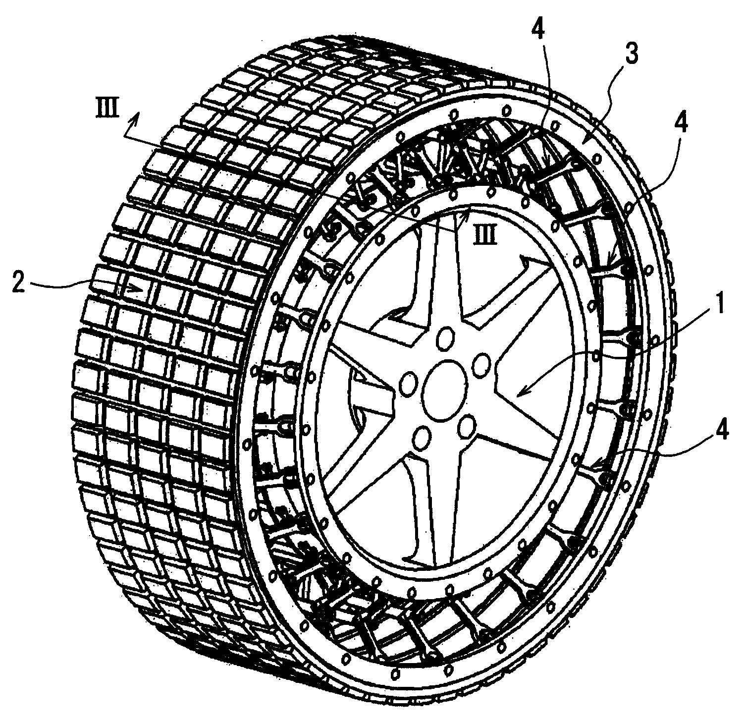
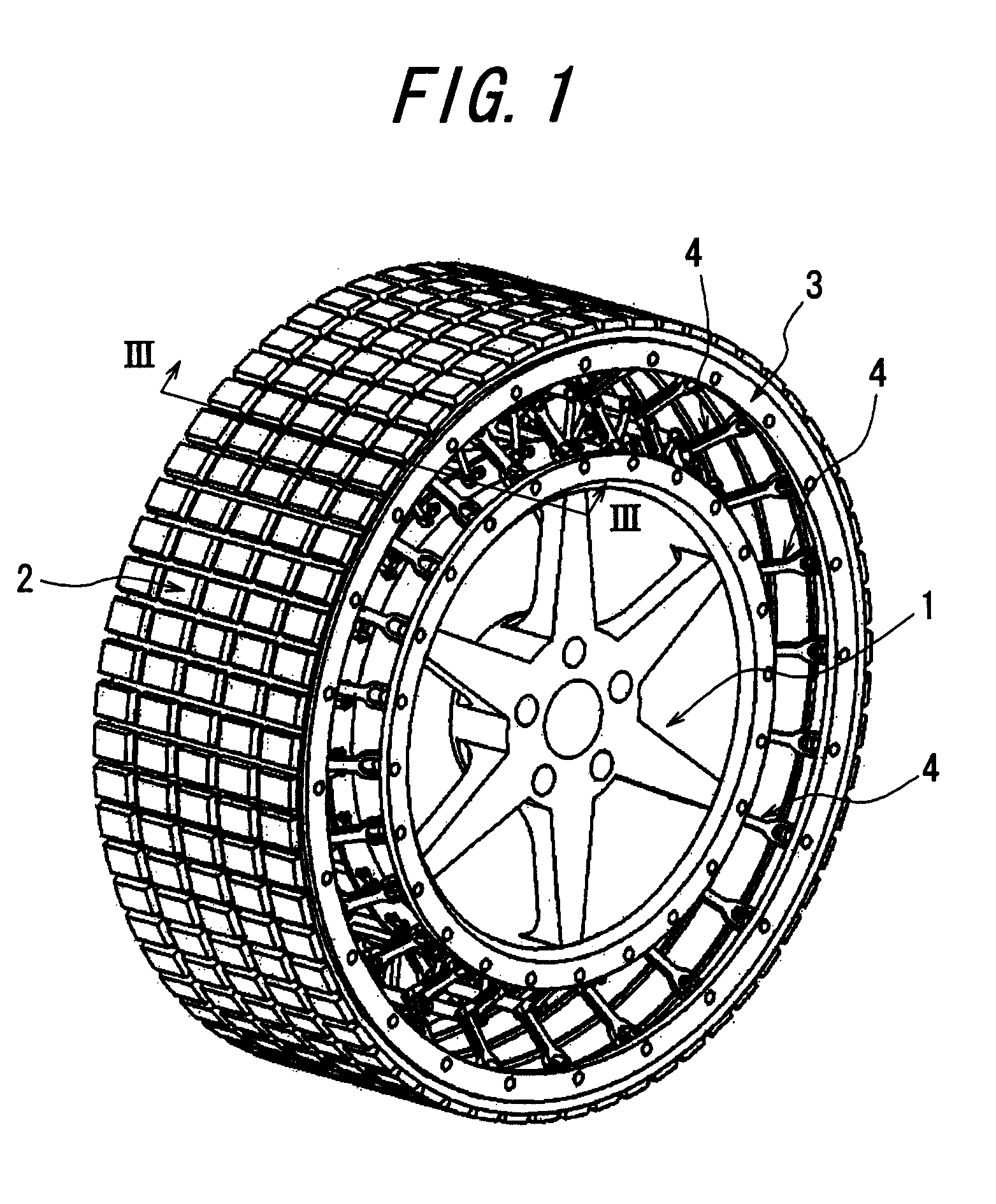
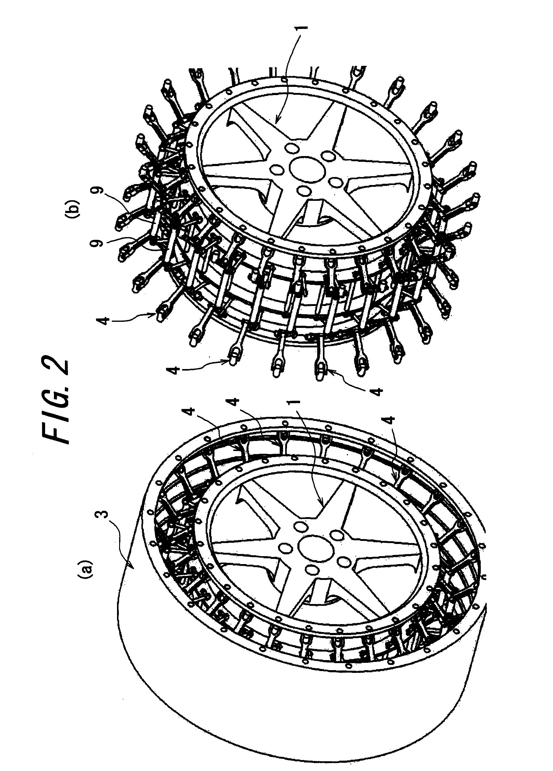
[0067]Example tire 1 has a basic structure as shown in FIGS. 1 and 2, and has a torsion bar 12 in addition to a coil spring as a spring member 9. Example tire 2 has a basic structure as shown in FIG. 8, and additionally has the same spring member 9 and a torsion bar 12. Further, both of Example tires 1 and 2 is provided with a torsion bar at the connections of the links 5a, 5b to the rim member 1.

[0068]The riding comfort is evaluated from a feeling obtained by an actual vehicle traveling test in which the tire wheel is mounted on a passenger vehicle of 3000 cc displacement and tested under a load condition corresponding to two passengers. The driveability is evaluat...


PUM


Abstract

There is provided a non-pneumatic tire which can eliminate a necessity of filling a pressurized air or other gases to obviate a possibility of decrease or loss of the internal pressure of the tire and which can easily provide desired vertical, longitudinal and lateral stiffnesses in a mutually independent state.The non-pneumatic tire has a rim member 1, a ring member 3 disposed at an outer circumferential side of the rim member 1 and provided with a tread 2 on a circumferential face, and a plurality of link mechanisms 4 coupling the rim member with the ring member. Each of the link mechanisms 4 consists of a pair of link members 7a, 7b consisting of a link 5a, 5b which is connected at a first end with a side portion of the rim member 1 and which is swingable in the circumferential and meridian directions and another link 6a, 6b which is connected at a first end with a side portion of the ring member and 3 which is swingable in the circumferential and meridian directions with second ends of the links being hingedly connected one another to make the links swingable in the meridian direction. A spring member 9 imparting a stiffness against relative displacements in the radian, circumferential and width directions with respect to the rim and ring members 1, 3 is provided on the link mechanisms 4.

Description

TECHNICAL FIELD[0001]The present invention relates to a non-pneumatic tire. More particularly, the present invention proposes a technique capable of eliminating a necessity of filling a pressurized air and easily providing vertical, longitudinal and lateral stiffnesses of required magnitudes to a tire.RELATED ART[0002]A pneumatic tire is a widely and commonly used for motor vehicles and the like, but it has an unavoidable drawback that filled-air pressure is decreased and even lost due to a puncture or the like.DISCLOSURE OF THE INVENTIONProblems to be Solved by the Invention [0003]In view of this drawback, various kinds of non-pneumatic tires which can eliminate a necessity of filling a pressurized air have been proposed. One example of such a non-pneumatic tire is a solid tire having a solid structure, but it involves another drawbacks of increasing both of the weight and hardness, so that, as compared with a pneumatic tire, sufficient riding comfort and driveability cannot be sec...

Claims


Application Information

Patent Timeline
Patent Type & Authority Applications(United States)
IPC IPC(8): B60C7/24
CPCB60C7/102Y10T152/10B60C7/14
Inventor ABE, AKIHIKO
Owner BRIDGESTONE CORP
Learn More