
Handoff method for communication system using multiple wireless resources

Inactive Publication Date: 2008-03-06
HITACHI LTD
View PDF14 Cites 16 Cited by
  • Summary
  • Abstract
  • Description
  • Claims
  • Application Information

AI Technical Summary

Benefits of technology

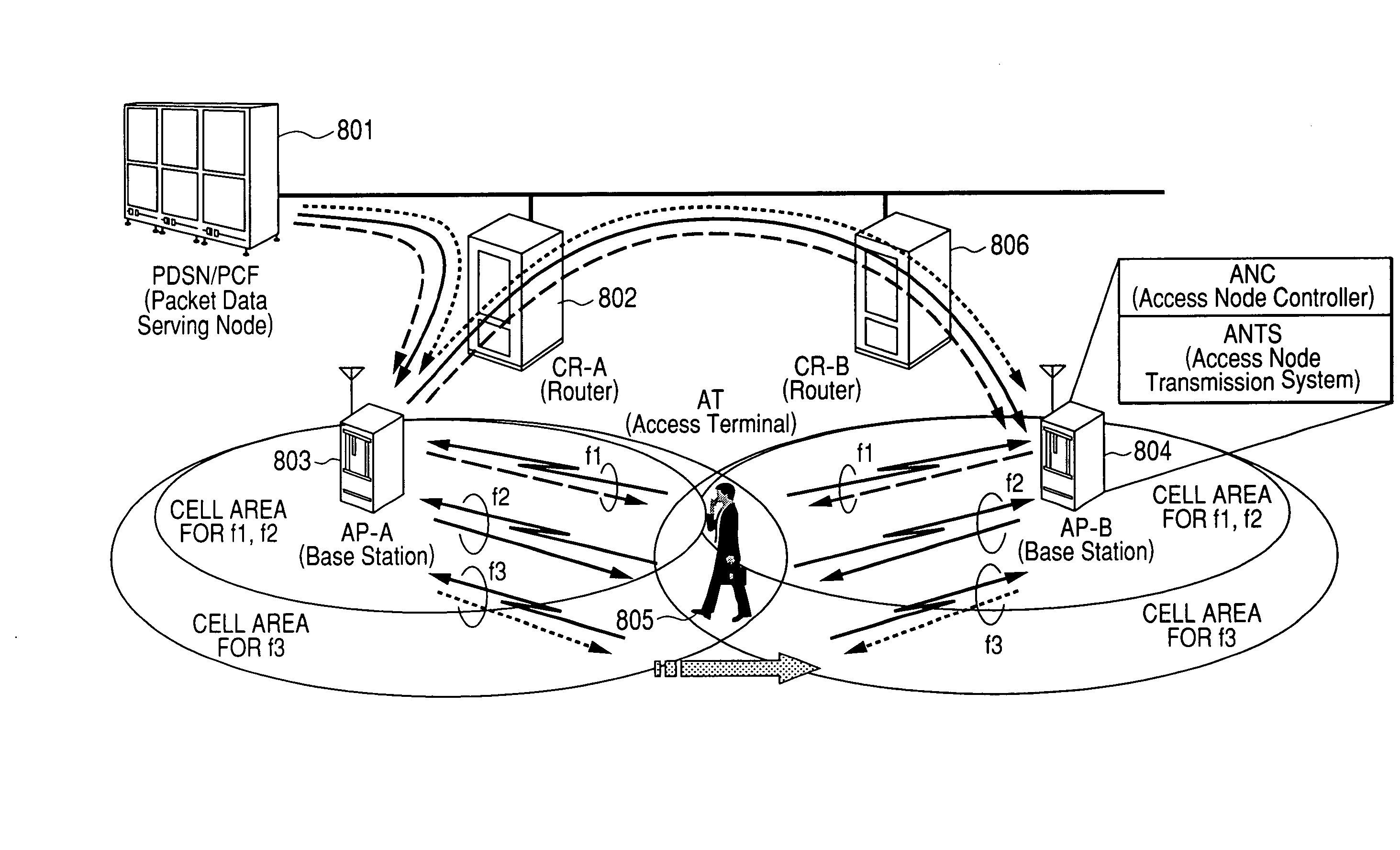
[0019] Next, soft handoff in a second network configuration will be described using FIG. 8. In this configuration, ANC is installed in each AP, and APs are connected by a CR (Router). Downlink circuit transmission data at the carrier frequencies f1-f3 is passed from the PDSN (Packet Data Serving Node) 801 via CR-A (Router), and is first transmitted from an AP (Access Point)-A803 to an AT (Access Terminal) 805. The AP 803 (804) has functions corresponding to both ANC 102 and ANTS 103 in FIGS. 1-3. In this configuration, when soft handoff is performed, ANC in AP-A803 is the main element which forwards data to AP-B 804 via CR-A 802 and CR-B 806, and soft handoff is performed between AP-A 803 and AP-B 804 which are contained in the Active Set of the terminal 805. In this configuration also, if the soft handoff state persists for a long time, network resources are consumed due to forwarding of data between AP-A 803 and AP-B 804, and it was therefore important to reduce the soft handoff procedure time.
[0022] According to an embodiment of the present invention, a soft handoff period when one terminal communicates using multiple carriers at the same time is shortened, sufficient received strength in the terminal is maintained, and the mobility of the terminal is guaranteed, while on the other hand, a network forwarding load, terminal processing load and wireless resource allocation time can be suppressed to the minimum.

Problems solved by technology

If you try to enhance the communication capability for each terminal N times by using N carriers with the conventional soft handoff method, the efficiency and the stability will become problems.

Method used


Image

  • Handoff method for communication system using multiple wireless resources
  • Handoff method for communication system using multiple wireless resources
  • Handoff method for communication system using multiple wireless resources

Examples


embodiment 1

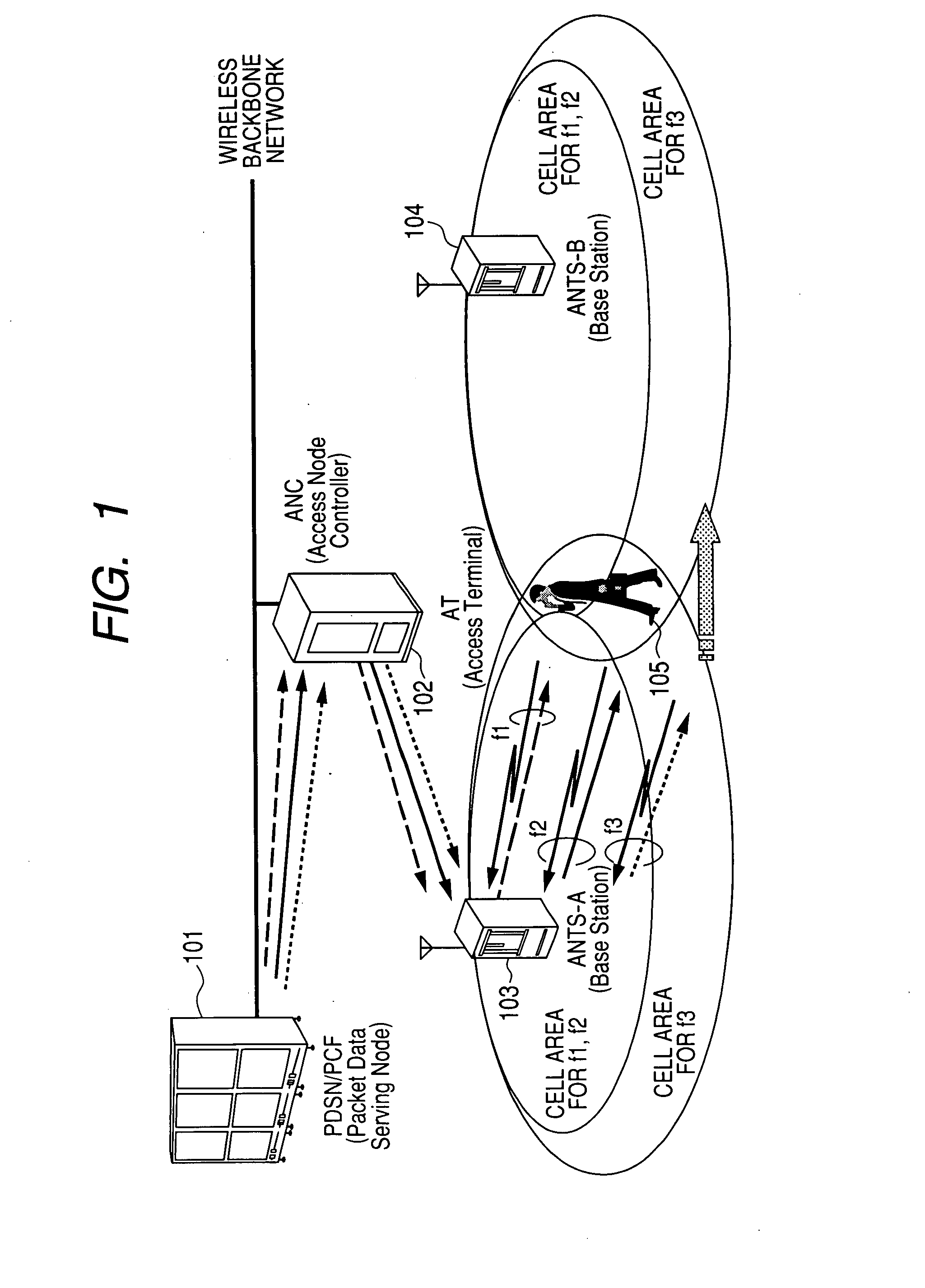
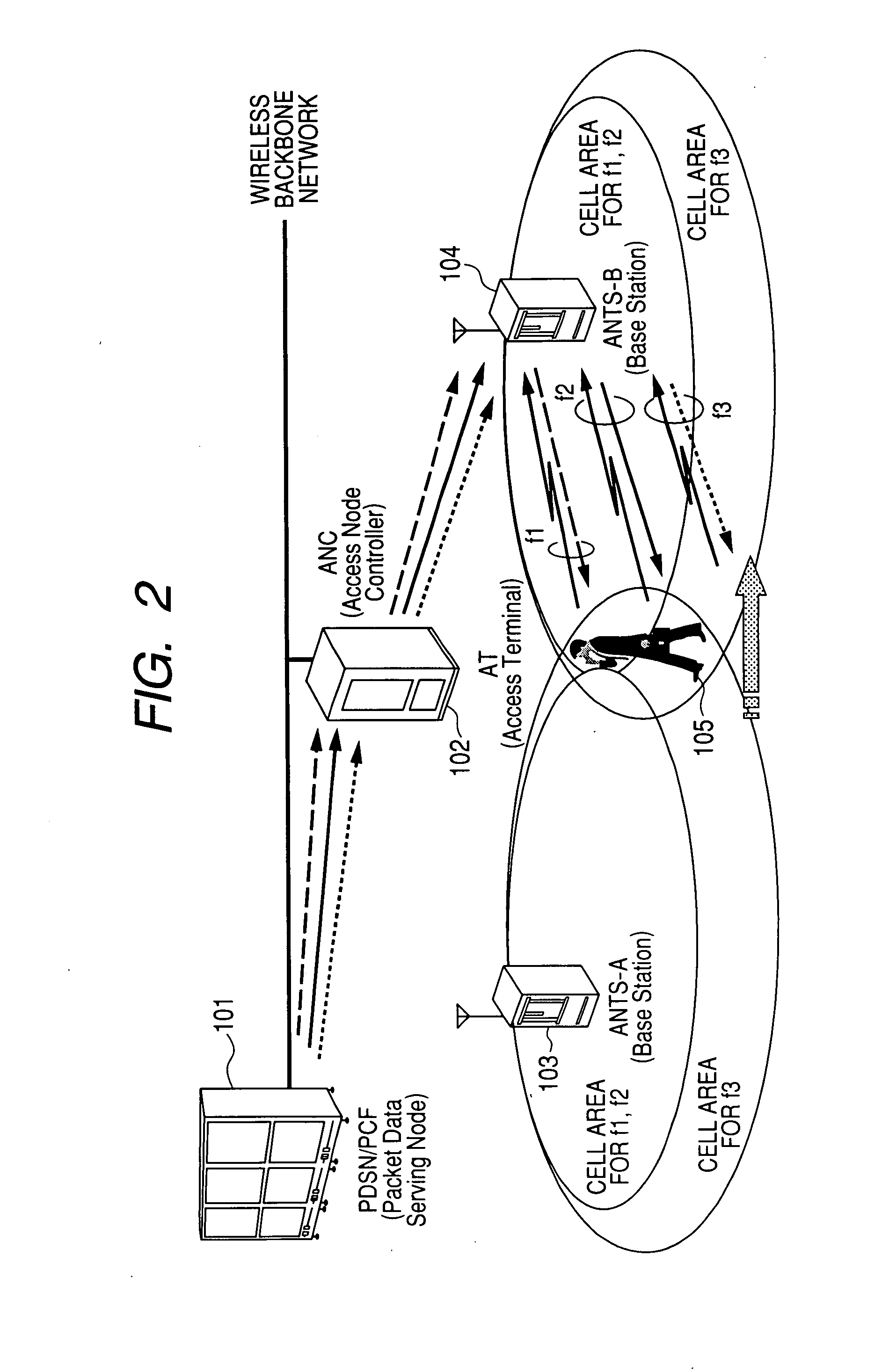
[0036] A first embodiment of the present invention will now be described referring to FIG. 5. In this embodiment, a first example of a network configuration is shown in FIG. 3. In this embodiment, the salient points are that soft handoff termination is periodically determined, and stability is maintained while redundant soft handoff is avoided. To ensure above points, soft handoff is terminated on the basis of the following sequences.

Sequence (500)

[0037] It is assumed that soft handoff is performed at three frequencies (f1, f2, f3). The procedure for this will be described. Soft handoff at these frequencies may be performed at the same time, or soft handoff may be performed one by one according to the propagation situation. The Active Set of each terminal is managed for each carriers. This is in agreement with sequences (401)-(404) described in FIG. 4. The messages for f1-3 up to sequence (501) show that for carriers f1 and f2, since the receiving signal quality from ANTS-B is be...

embodiment 2

[0056]FIG. 9 shows a flow chart when applying the first embodiment in the aforesaid second network configuration. In this embodiment, as in the first embodiment, a soft handoff termination judgment is made periodically, and a prolonged soft handoff state is avoided while maintaining stability.

[0057] Hence, soft handoff is terminated based on the following sequences.

Sequence (900)

[0058] It is assumed that there is a soft handoff state at three frequencies (f1, f2, f3). The procedure for this will now be described. These may be in a soft handoff state simultaneously, or may be in a soft handoff state one by one according to the transmission state. This is equivalent to the sequences (401)-(404) described in FIG. 4. The difference is that since ANC in FIG. 4 is divided into multiple parts, data is sent from PCF / PDSN to ANC-A which is the origin of soft handoff until soft handoff is completed, and when soft handoff is completed, the soft handoff target is changed to ANC-B. During so...

embodiment 3

[0063] A third embodiment will now be described referring to FIG. 7. In this embodiment, when a RouteUpdate message for soft handoff termination is received from the terminal for one carrier among multiple carriers (equivalent to sequence 405), the same soft handoff termination judgment is made as in the case of the first embodiment (701). For example, as shown by 500 of FIG. 5, when there is a soft handoff state for all the carriers f1-f3 and an instruction to terminate soft handoff for f1 is notified from the terminal side, it is instructed to terminate soft handoff also for the carriers f2, f3 which are still in the soft handoff state.

[0064] Also in this case, by shortening the soft handoff period, operating efficiency of wireless resources can be increased and terminal battery consumption can be reduced. As compared with the case of the first embodiment which periodically judges the feasibility of disconnection of ANTS-A continuously from soft handoff Start, the risk of “discon...


PUM


Abstract

In a wireless communications system operating according to CDMA or the like, when one terminal simultaneously performs communication using multiple wireless resources (e.g., multiple carriers), there was a problem that when it was attempted to guarantee network mobility by the same soft handoff system as in the case where communication was performed using only one wireless resource, efficiency suffered from the viewpoint of network forwarding load, processing load and wireless resource occupancy time. Soft handoff termination is judged and soft handoff is forcibly terminated according to whether or not the data rate obtained for all resources on the network side satisfies a requested rate, based on a reception state notification from a terminal concerning wireless resources. By performing this processing, the soft handoff period is shortened, sufficient received strength in the terminal is maintained and terminal mobility is guaranteed, while at the same time network forwarding load, terminal processing load and wireless resource occupancy time are suppressed to the absolute minimum.

Description

CLAIM OF PRIORITY [0001] The present application claims priority from Japanese application JP 2006-234897 filed on Aug. 31, 2006, the content of which is hereby incorporated by reference into this application. FIELD OF THE INVENTION [0002] The present invention is suitable for wireless communications systems terminals and base stations that support terminal mobility such as mobile phones and wireless LAN, and particularly, for those using MC-CDMA (multi carrier code division multiple access). BACKGROUND OF THE INVENTION [0003] Wireless communications systems such as mobile phones aim to enable communication “anytime and anywhere” without interruption, and have developed to support the expansion of communication areas and handoff technology between base stations. [0004] Recently, the data amount being exchanged by a single user has been rapidly increasing, such as E-mails with photographic or moving image files attached, and motion picture of Video phones for example. Wireless commun...

Claims


Application Information

Patent Timeline
IPC IPC(8): H04Q7/20H04W36/18H04W36/28
CPCH04W36/28H04W36/18
Inventor TAKADA, MAYTAKAHASHI, YOSUKEMAZAWA, SHIROKATAYAMA, RINTARO
Owner HITACHI LTD
Learn More