
Automobile top fin antenna capable of enhancing signal strength

A technology for enhancing signals and automobiles. It is applied in the directions of antennas, antennas, and antenna parts suitable for movable objects. It can solve the problems of loss of functions such as automobile communication, and reduction of signal strength capabilities, so as to accelerate heat loss and improve usage. life, and the effect of improving the reception strength of the antenna signal

Pending Publication Date: 2020-09-01
童爱霞
View PDF10 Cites 0 Cited by
  • Summary
  • Abstract
  • Description
  • Claims
  • Application Information

AI Technical Summary

Problems solved by technology

When the antenna is generally used in towns, the signal reception is better, but once the car drives to the countryside, where there are fewer signal towers, the signal strength will decrease, resulting in the loss of the car's communication and other functions

Method used


Image

  • Automobile top fin antenna capable of enhancing signal strength
  • Automobile top fin antenna capable of enhancing signal strength
  • Automobile top fin antenna capable of enhancing signal strength

Examples


Embodiment 1

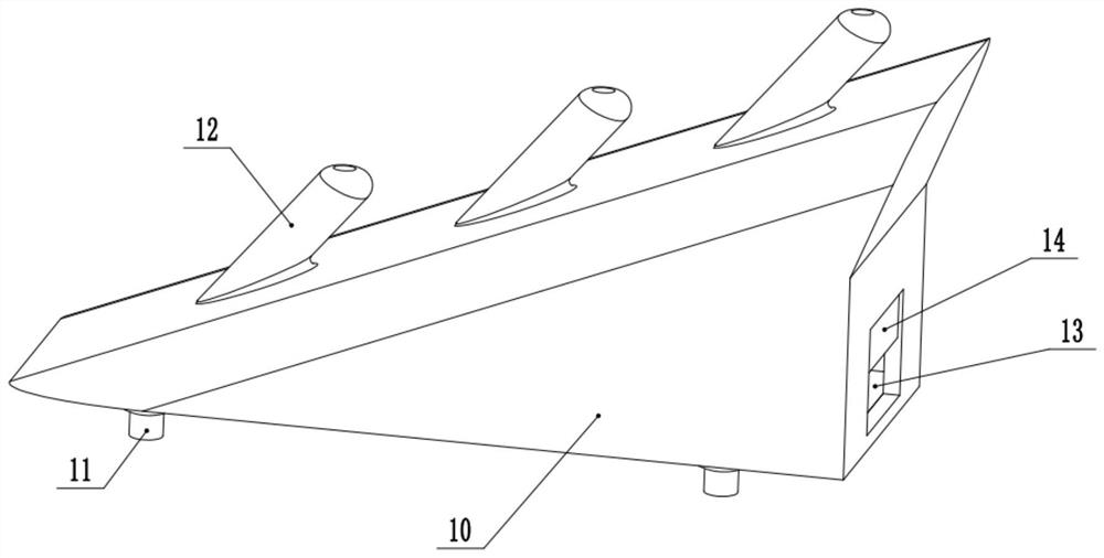
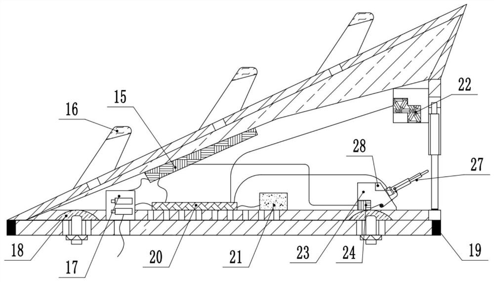
[0022] see Figure 1-2 , a car top fin antenna that can enhance the signal strength, including a housing 10, a main antenna vibrator 15, a power supply 17, and a circuit board 20; 11 is fixedly installed on the top of the car, and the bottom of the casing 10 is wrapped with a ring of sealing ring 19 to prevent water leakage when the casing 10 is installed on the top of the car. The position where the fixing bolt 11 is placed inside the shell 10 is provided with a semicircular concrete foam cavity 18, and the top of the fixing bolt 11 is set inside the concrete foam cavity 18, thereby blocking the contact between the fixing bolt 11 and the internal parts of the shell 10 Case. On the left side of the inner bottom of the housing 10 is fixed a group of power sources 17 electrically connected to the internal power supply of the vehicle. The power sources 17 are used to provide electrical energy for the operation of the electrical components inside the housing 10 . The right side ...

Embodiment 2

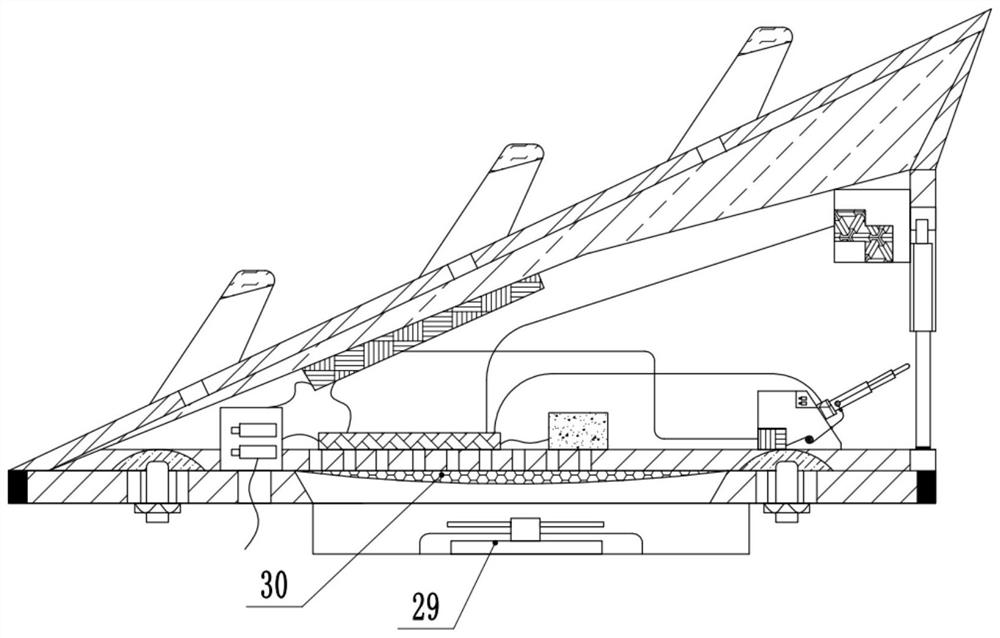
[0025] refer to image 3 , on the basis of Embodiment 1, a group of exhaust fans 29 are fixedly installed on the bottom of the lower surface of the housing 10, and the output end of the exhaust fan 29 is connected upwards with an air outlet, and a set of air outlets is provided in the bottom wall of the housing 10 above the air outlet. The air outlet meshes 30 penetrating through the upper and lower sides of the dry set can output the air inside the housing 10 downward by starting the exhaust fan 29 downward, thereby reducing the heat generated by the internal components of the housing 10 during operation.

[0026]The working principle of the present invention is: the housing 10 is fixedly installed on the top of the car by the fixing bolt 11, then the signal is received by the signal receiving end 16 arranged on the outer top of the housing 10, and then the signal is received through the main antenna vibrator 15, the circuit board 20, the Beidou medium Antenna 21 performs ana...


PUM


Abstract

The invention relates to the technical field of communication equipment, and discloses an automobile top fin antenna capable of enhancing the signal intensity. The automobile top fin antenna comprisesa shell, a main antenna oscillator, a power supply and a circuit board, wherein a signal enhancement rod with an inclination angle similar to that of the top of the shell is fixedly mounted at the outer top of the shell; a signal receiving end for receiving signals is arranged at the inner top of the signal enhancement rod; a rectangular telescopic rod inlet / outlet is outwards formed in the lowerpart of the right side wall of the shell; an electric baffle capable of moving up and down is upwards arranged in the telescopic rod inlet / outlet; the upper right side of the telescopic rod base is arranged to be of an inclined surface structure and is fixedly provided with a set of telescopic rods, the top ends of the telescopic rods are provided with signal receiving ends, and the signal receiving ends at the top ends of the telescopic rods are electrically connected with auxiliary antenna oscillators arranged on the left side in the telescopic rod base. The automobile top fin antenna has the advantages that the signal receiving capacity can be automatically adjusted, normal operation of communication in the automobile is ensured, automatic operation is achieved, and the use value is high.

Description

technical field [0001] The invention relates to the technical field of communication equipment, in particular to an automobile top fin antenna capable of enhancing signal strength. Background technique [0002] Shark fin type vehicle antenna has a relatively low height and a beautiful appearance. The helical antenna vibrator is used in the shell, and the helical antenna is a slow wave system. The propagation velocity of the electromagnetic wave in the axial direction of the helix is ​​much smaller than the velocity in the air, so the wavelength is correspondingly much shorter, and it has good signal receiving ability. [0003] Chinese patent (notification number: CN 203326081 U, announcement date: 2013.12.04) discloses a shark fin antenna, which includes: a housing, an antenna vibrator, a skeleton, a first skeleton ambush, a second skeleton ambush, a hollow inductor, GPS / Beidou dielectric antenna, terminals, circuit boards, backplane clamps, backplanes, rubber rings, GPS / ...

Claims


Application Information

Patent Timeline
Patent Type & Authority Applications(China)
IPC IPC(8): H01Q1/12H01Q1/18H01Q1/32H01Q1/36H01Q1/42
CPCH01Q1/12H01Q1/18H01Q1/3275H01Q1/36H01Q1/428
Inventor 纪建德
Owner 童爱霞
Learn More