Measuring device for ultra-deep resistivity
A measuring device and resistivity technology, which is applied in the field of ultra-deep resistivity measuring devices, can solve problems such as failure to discover geological layered structures in time, limited forward detection depth, drilling through oil layers, etc., to increase strength and save hardware Overhead, the effect of reducing power consumption
- Summary
- Abstract
- Description
- Claims
- Application Information
AI Technical Summary
Problems solved by technology
Method used
Image
Examples
Embodiment 1
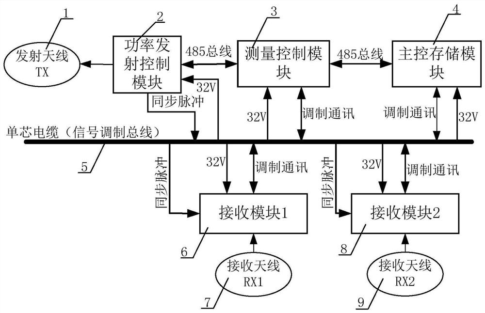
[0050] The embodiment of the present invention provides a measurement device for ultra-deep resistivity, such as figure 1 shown, including:
[0051] The measurement control module 3, as the control center of the entire measurement device, enables the power transmission control module 2 to output a square wave transmission signal of a certain fixed frequency, and performs related FFT conversion and delay characteristic analysis on the sampled measurement data, and obtains Output the final resistivity data, communicate with the main control storage module 4, and upload the data in real time to the main control storage module 4FLASH for storage;
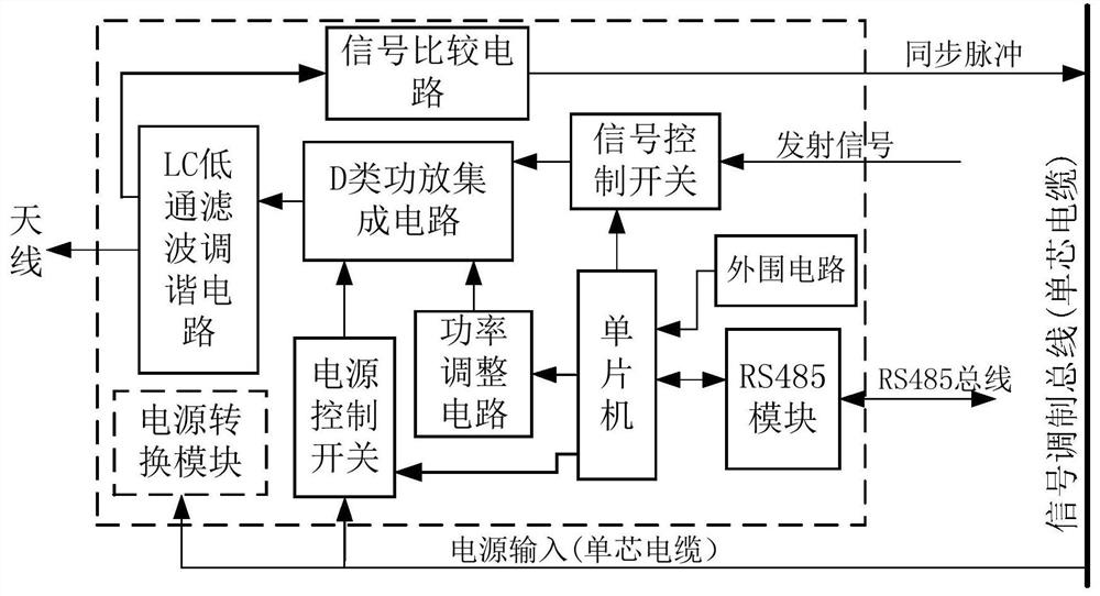
[0052] The power transmission control module 2 is used to receive the sine wave signal, and amplify the sine wave signal through a class D power amplifier circuit and output it to the transmitting antenna 1;
[0053] The transmitting antenna 1 is used to receive the amplified sine wave signal, and excite a periodic high-power sine wave...
Embodiment 2
[0080] Embodiments of the present invention provide a method for measuring ultra-deep resistivity, such as Figure 9 shown, including the following steps:
[0081] A1. The instrument is powered on, the module circuit units of the measurement control module 3, the power transmission control module 2, the main control storage module 4, the first receiving module 6 and the second receiving module 8 are powered on and initialized, and the measuring device completes the self-test and is in the In the standby state, the signal modulation bus 5 is in an idle state, and the signal modulation bus 5 is a single-core cable.
[0082] A2. The instrument enters the low power consumption mode. The main control storage module 4 waits to receive the central control command on the signal modulation bus 5 and parses it. If the resolution is a parameter modification command or other commands, then enter step A3. If the resolution is a start measurement command, then enter Step A4;
[0083] When...
PUM
 Abstract
Description
Claims
Application Information
 - R&D
- Intellectual Property
- Life Sciences
- Materials
- Tech Scout
- Unparalleled Data Quality
- Higher Quality Content
- 60% Fewer Hallucinations
Browse by: Latest US Patents, China's latest patents, Technical Efficacy Thesaurus, Application Domain, Technology Topic, Popular Technical Reports.
© 2025 PatSnap. All rights reserved.Legal|Privacy policy|Modern Slavery Act Transparency Statement|Sitemap|About US| Contact US: help@patsnap.com


