Eureka AIR delivers breakthrough ideas for toughest innovation challenges, trusted by R&D personnel around the world.

Dynamic modeling of an internal combustion engine operating with multiple combustion modes

a technology of internal combustion engine and combustion mode, which is applied in the direction of electric control, machines/engines, instruments, etc., can solve the problems of inability to meet the emission levels mandated for the future, inability to meet the emission levels of conventional diesel alone, and sensitive to engine conditions. , to achieve the effect of reducing the number of in-cylinder conditions

Active Publication Date: 2008-02-14
SOUTHWEST RES INST
View PDF16 Cites 18 Cited by
  • Summary
  • Abstract
  • Description
  • Claims
  • Application Information

AI Technical Summary

Benefits of technology

[0011] Once the model is developed, additional software can be used to develop an engine controller that can accept various engine conditions and achieve desired performance. After developing and tuning the control system through simulations, control system programming is easily generated for production-level controller hardware. In sum, good engine models are indispensable for a transition from a rapid prototyping controller to a production-level controller.

Problems solved by technology

In recent years, it has become apparent that conventional diesel combustion cannot alone meet emission levels mandated for the future.
However, because the applicable speed-load regions of different combustion modes are different from each other, the engine must seamlessly switch among these modes.
Some modes are close to the edge of unstable combustion, and are very sensitive to engine conditions.
However, in-cylinder conditions change at a much slower rate (over several combustion cycles).
Poor control over in-cylinder conditions not only diminishes the merits of alternate combustion modes but also worsens drivability and emissions.

Method used


Image

  • Dynamic modeling of an internal combustion engine operating with multiple combustion modes
  • Dynamic modeling of an internal combustion engine operating with multiple combustion modes
  • Dynamic modeling of an internal combustion engine operating with multiple combustion modes

Examples


Embodiment Construction

[0009] Dynamic Engine Model as Basis for Control System

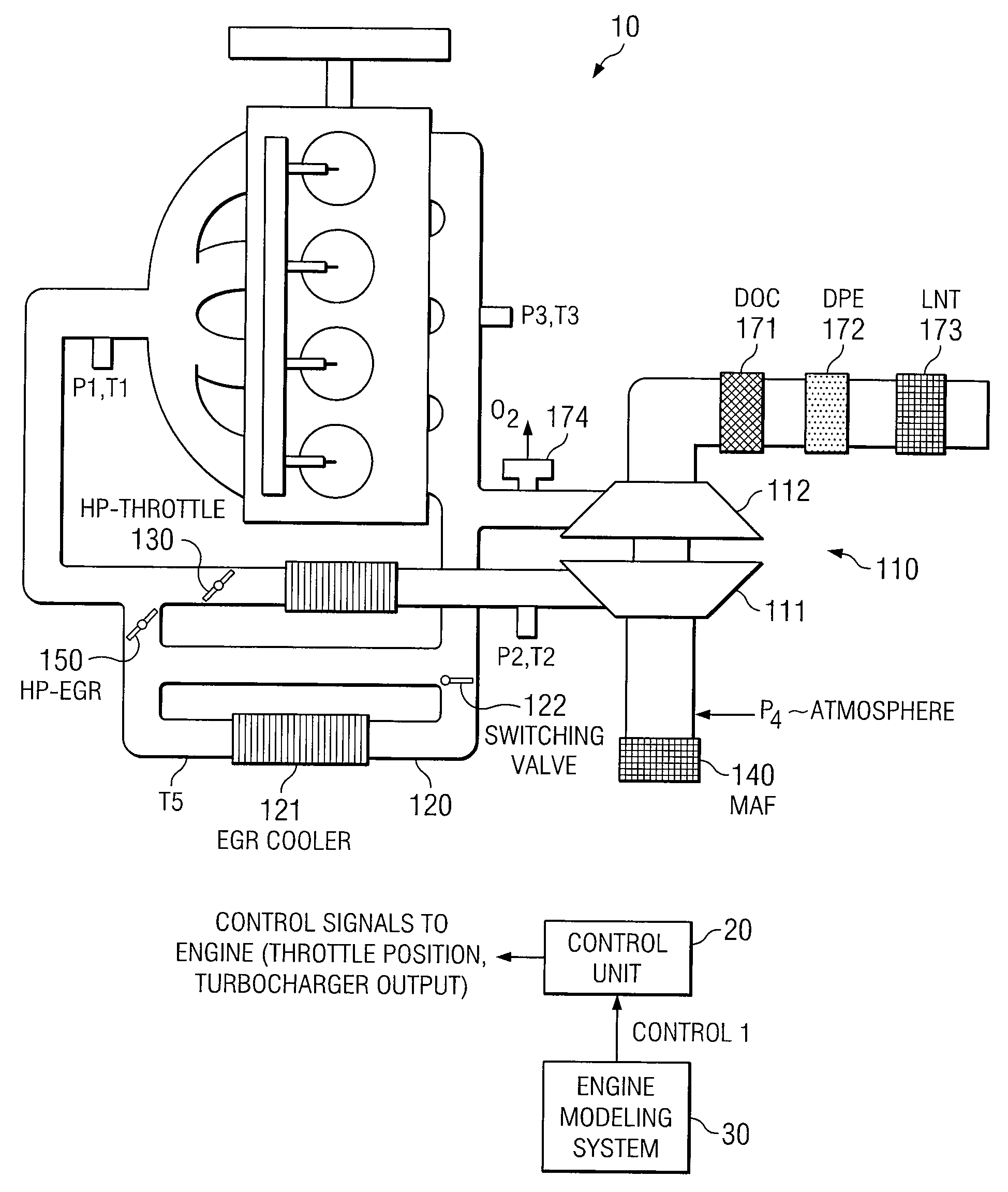
[0010] One approach to designing control systems for engine in-cylinder conditions is to first develop a dynamic model of the engine. The model can be implemented in a graphical simulation environment, using real or simulated engine conditions as inputs. Appropriate software is used to build the model and to manage data.

[0011] Once the model is developed, additional software can be used to develop an engine controller that can accept various engine conditions and achieve desired performance. After developing and tuning the control system through simulations, control system programming is easily generated for production-level controller hardware. In sum, good engine models are indispensable for a transition from a rapid prototyping controller to a production-level controller.

[0012] For purposes of this invention, the modeling is of the intake and exhaust of an engine operating with multiple combustion modes. The dynamics of va...


PUM


Abstract

A method of modeling a diesel engine that is capable of multiple combustion modes and equipped with a turbocharger and EGR loop. The model comprises a set of equations, each equation representing one of the following as a time derivative: pressure at the intake manifold, pressure between the turbine and an intake manifold throttle, pressure at the exhaust manifold, the compressor power, and the fresh air fraction (the ratio of fresh air to EGR). The model is used to determine what engine conditions (such as throttle positions and turbocharger output) will result in desired pressures and fresh air fraction.

Description

RELATED PATENT APPLICATION [0001] This application claims the benefit of U.S. Provisional Application No. 60 / 836,818, filed Aug. 10, 2006 and entitled “DYNAMIC MODELING OF AN INTERNAL COMBUSTION ENGINE OPERATING WITH MULTIPLE COMBUSTION MODES.”TECHNICAL FIELD OF THE INVENTION [0002] This invention relates to control systems for internal combustion engines, and more particularly to a control system for an internal combustion engine having multiple combustion modes. BACKGROUND OF THE INVENTION [0003] In recent years, it has become apparent that conventional diesel combustion cannot alone meet emission levels mandated for the future. Hence, diesel engine manufacturers have been considering multiple combustion modes as a means to reduce emissions. Alternate combustion modes such as homogeneous charge compression ignition (HCCI), low temperature combustion (LTC), and premixed charge compression ignition (PCCI) are being developed and implemented on diesel engines, together with conventio...

Claims


Application Information

Patent Timeline
Patent Type & Authority Applications(United States)
IPC IPC(8): G06G7/64
CPCF02B29/0406Y02T10/47F02D41/0007F02D41/0072F02D41/3035F02D2041/007F02D2041/1433F02D2200/0402F02M25/0707F02M25/0728F02M25/0754G06F17/5095G06F2217/80Y02T10/144F02D23/02F02M26/05F02M26/25F02M26/47G06F30/15G06F2119/08Y02T10/12Y02T10/40
Inventor WANG, JUNMIN
Owner SOUTHWEST RES INST
Why Eureka
Eureka Blog
Learn More