
Composite component

a composite component and component technology, applied in the field of composite components, can solve the problems of high cost of assembly of these components, limited use of plastic in such applications, and relatively heavy steel materials, and achieve the effects of easy integration, easy recycling, and reduced weight of composite components

Active Publication Date: 2008-02-14
BASF AG
View PDF37 Cites 88 Cited by
  • Summary
  • Abstract
  • Description
  • Claims
  • Application Information

AI Technical Summary

Benefits of technology

The present invention is a composite component that integrates a thermoplastic material and a reinforcing composite layer to create a strong and lightweight component that can withstand loads. The method of forming the composite involves heating the thermoplastic material and disposing it in contact with the reinforcing composite layer, resulting in a seamless connection that combines the two materials. The composite component is easy to recycle and can be made from recyclable materials. The technical effects of the invention include improved strength and durability, reduced weight, and easy recycling.

Problems solved by technology

For example, cargo may move in the vehicle if the cargo is not secured and the vehicle is involved in an accident.
However, the steel seat back is comprised of several individual components and the assembly of these components makes such a construction relatively expensive.
Additionally, steel is a relatively heavy material.
However, the use of plastic in such applications is limited due to the relatively low stiffness and low impact strength of plastic in comparison to steel.
As a result, seat backs made from plastic may be too thick to accommodate packaging constraints in vehicles.
Adequate interaction between the plastic of the support portion and the metal of the reinforcement portion is difficult to obtain.
Further, such a seat back is not easily recyclable because the seat back is formed of both plastic and metal.

Method used


Image

  • Composite component
  • Composite component
  • Composite component

Examples


Embodiment Construction

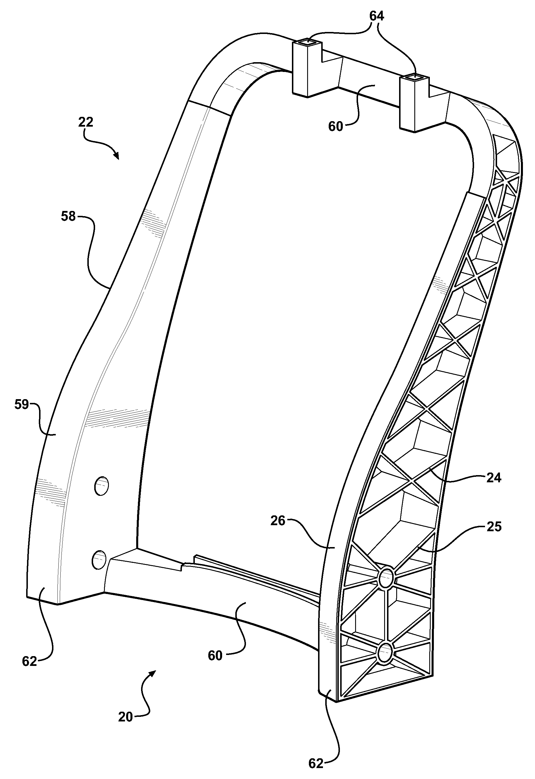
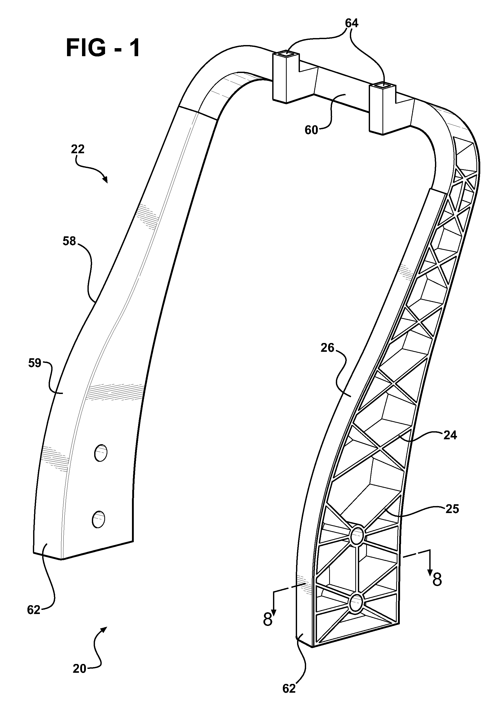
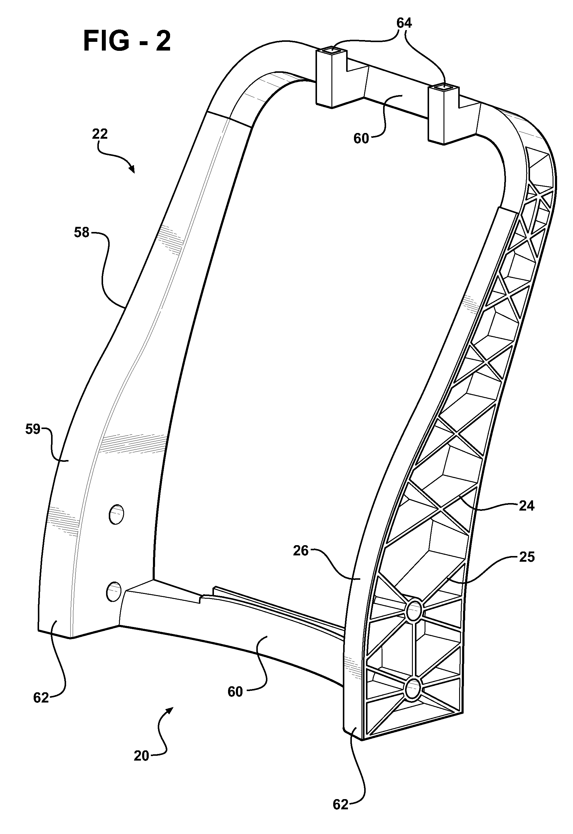
[0029]Referring to the Figures, wherein like numerals indicate corresponding parts throughout the several views, a composite component, is shown generally at 20. It should be appreciated that the composite component 20 may be any type of composite component 20 for a variety of uses. For example, the composite component 20 may be a seat back 22 or a structural beam (not shown). In the embodiments shown in the Figures, the composite component 20 is the seat back 22 for a vehicle, such as an automobile. The seat back 22 is assembled in a seat assembly (not shown) including a seat bottom extending generally horizontally for supporting a seated passenger or cargo. It should be appreciated that the seat back 22 may be used in any type of vehicle including, for example, a bus, an airplane, and a boat. Although not required, the seat back 22 typically includes foam surrounding the support portion 24 and the reinforcing composite layer 26 and a covering over the foam.

[0030]As shown in FIGS. ...


PUM

PropertyMeasurementUnit
thickaaaaaaaaaa
melting temperatureaaaaaaaaaa

Abstract

A composite component such as a seat back for a vehicle comprises a support portion and at least one reinforcing composite layer. The support portion comprises a thermoplastic material and the reinforcing composite layer comprises a polymeric material impregnating a plurality of fibers. The polymeric material of the reinforcing composite layer is integrated with the thermoplastic of the support portion. A method of forming the composite component includes placing the composite layer into a mold, heating the thermoplastic material to a molten state, and disposing the thermoplastic material in the molten state into contact with the composite layer. The method further includes promoting interaction between the thermoplastic material and the polymeric material to integrate the support portion and the reinforcing composite layer. The thermoplastic material supports the reinforcing composite layer and the reinforcing composite layer reinforces the thermoplastic material to prevent failure when subjected to a load.

Description

CROSS-REFERENCE TO RELATED APPLICATIONS[0001]The subject patent application claims priority to and all the benefits of U.S. Provisional Patent Application Ser. No. 60 / 822,319 which was filed on Aug. 14, 2006, the entire specification of which is incorporated herein by reference.BACKGROUND OF THE INVENTION[0002]1. Field of the Invention[0003]The present invention is related to a composite component including a support portion and a reinforcement composite layer and a method of forming the same.[0004]2. Description of the Related Art[0005]A composite component is formed of at least two diverse materials that are combined together to form a single unit. Composite components are used in a variety of settings including seat backs for a vehicle and structural beams. Seat backs for vehicles are assembled in a seat assembly and the seat assembly is disposed in the vehicle, such as an automobile, for supporting occupants of the vehicle.[0006]Seat backs must meet structural requirements by ha...

Claims


Application Information

Patent Timeline
Patent Type & Authority Applications(United States)
IPC IPC(8): B32B27/06B29C70/68B60N2/90
CPCB60N2/68B29L2031/771B29C45/14786B60N2/64Y10T428/31504Y10T428/31732B60N2/00
Inventor EVANS, JONATHAN A.SCHLICKER, SCOTT C.LAMBI, MARIOS
Owner BASF AG
Learn More