
Heat conductor assembly of light source

a heat conductor and light source technology, applied in the field of lamps, can solve the problems of limited current in the prior art lamp, inability to effectively increase the power of the chip and the illumination of the lamp, and confine the illumination of leds lamps, e series lamps, mr series lamps, etc., to achieve the effect of increasing heat dissipation efficiency, and reducing heat dissipation tim

Inactive Publication Date: 2008-02-14
LI CHI MAO
View PDF4 Cites 7 Cited by
  • Summary
  • Abstract
  • Description
  • Claims
  • Application Information

AI Technical Summary

Benefits of technology

"The present invention provides a heat conductor assembly for a light source that improves heat dissipation efficiency. The assembly includes a lampshade cup made of heat conductive material, with at least one heat conductive sheet installed on the cup for contacting with a casing of a lamp so as to transfer heat. The periphery of the lampshade cup is formed with a plurality of heat conductive sheets, one end of each sheet is fixed to the lampshade cup, and another end thereof extends out from the lampshade cup to contact with the casing. The heat conductive sheet is cambered at one end to increase the contact area with the lamp casing, promoting faster heat dissipation. The assembly allows for better power and illumination of the light emitting diode, reducing the number of chips required and saving material costs. The casing acts as a heat dissipation portion, improving the lifespan of the light emitting elements."

Problems solved by technology

Thus current in the prior art lamp is limited.
The power of the chip and the illumination of the lamp cannot be increased effectively.
Thus, the E series lamps, MR series lamps, or LEDs lamps with standard joints are confined in illumination due to deficiency in heat dissipation.
As a result, these kinds of lamps have high cost, large volume, short lifetime and is thus not competitive commercially.

Method used


Image

  • Heat conductor assembly of light source
  • Heat conductor assembly of light source
  • Heat conductor assembly of light source

Examples


Embodiment Construction

[0013]In order that those skilled in the art can further understand the present invention, a description will be provided in the following in details. However, these descriptions and the appended drawings are only used to cause those skilled in the art to understand the objects, features, and characteristics of the present invention, but not to be used to confine the scope and spirit of the present invention defined in the appended claims.

[0014]Referring to FIG. 2, the heat conductor assembly of a light source of the present invention is illustrated. The present invention can be used to various bulbs. The heat conductor assembly of a light source has the following elements.

[0015]A lampshade cup 21 is a plurality of annular recesses 211 at an upper side thereof so as to increase the contact area between the lampshade cup 21 and air. Thus it has a preferred heat dissipation effect.

[0016]A heat conductive seat 22 is installed below the light heat conductor unit 2. A lower side of the h...


PUM


Abstract

A heat conductor assembly of a light source comprises a light emitting unit for illuminating light; a heat conductive seat for supporting the light emitting unit and having at least one pin or at least one joint for being connecting to a power source; and the heat conductive seat being heat conductive for dissipating heat from the light emitting element; a lampshade cup being made of heat conductive material; and at least one heat conductive sheet installed on the lampshade cup for contacting with a casing of a lamp so as to transfer heat; and thus the casing being formed as a heat dissipation portion. A periphery of the lampshade cup is formed with a plurality of heat conductive sheets, one end of each heat conductive sheet is fixed to the lampshade cup, and another end thereof extends out from the lampshade cup to contact with the casing.

Description

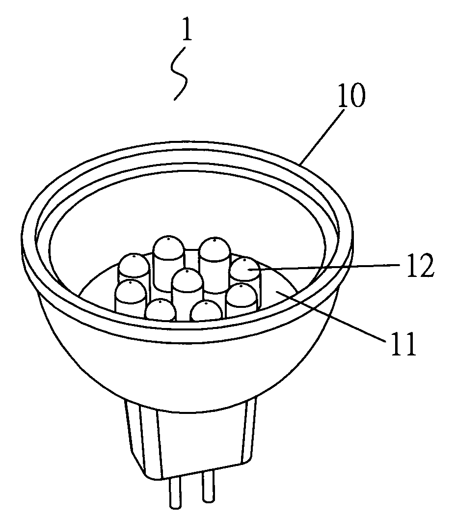
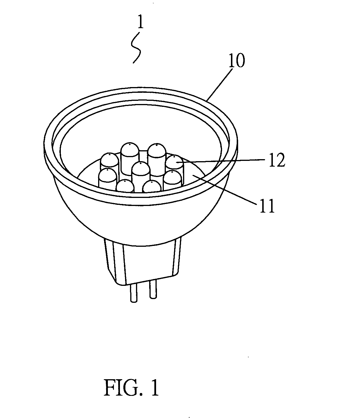
FIELD OF THE INVENTION[0001]The present invention relates to lamps, in particular to a heat conductor assembly of a light source, wherein a plurality of longitudinal recesses are formed at the periphery of the lampshade cup for retaining the heat conductive sheet so as to enlarge the contact area with air. Thus, the heat dissipation efficiency is increased. A plurality of heat conductive sheets are installed at a periphery of a lampshade cup and are spaced equally. One end of each heat conductive sheet is cambered so as to increase the contact area with lamp casing so that heat can be dissipated more rapidly. Furthermore, power and illumination of the light emitting diode can be promoted greatly so that the chips required are less than the prior art. Thereby the light emitting elements have longer lift time. The cost of material is saved.BACKGROUND OF THE INVENTION[0002]Referring to FIGS. 1 and 1-1, a prior art lamp 1 with LEDs light source is illustrated. The prior art is widely us...

Claims


Application Information

Patent Timeline
Patent Type & Authority Applications(United States)
IPC IPC(8): F21V29/00
CPCF21S48/328F21V29/004F21Y2101/02F21V29/83F21K9/137F21V29/74F21K9/135F21K9/232F21K9/233F21S45/48F21Y2115/10F21V19/0085F21V29/71F21V29/85
Inventor LI, CHI-MAO
Owner LI CHI MAO
Learn More