
Oxygen Transport Structure

a transport structure and oxygen technology, applied in solid-state devices, organic semiconductor devices, inorganic chemistry, etc., can solve the problem that the conductivity of room-temperature oxygen is normally of little use in real-world applications, and achieve the effect of high surface activation

Inactive Publication Date: 2008-02-14
HILLIARD DONALD BENNETT
View PDF3 Cites 21 Cited by
  • Summary
  • Abstract
  • Description
  • Claims
  • Application Information

AI Technical Summary

Benefits of technology

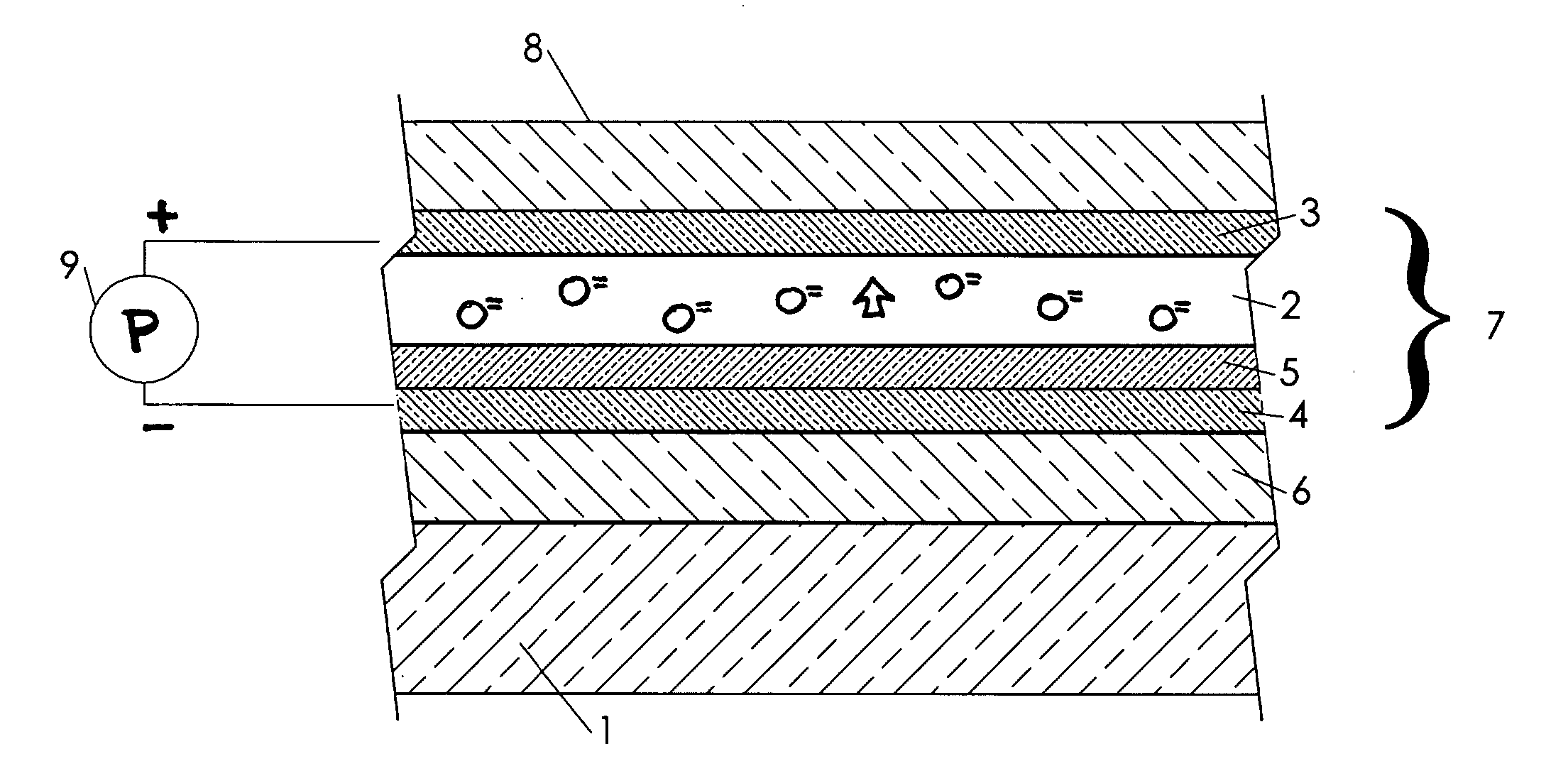
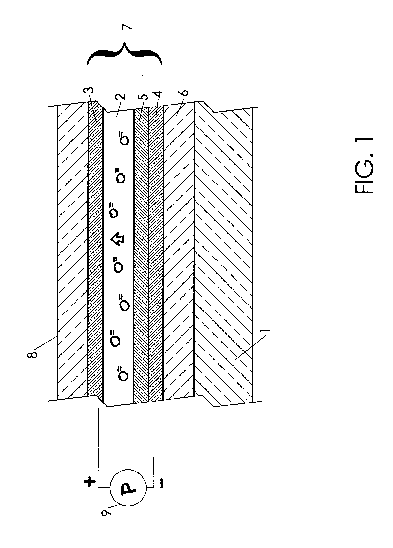
[0018] In its first preferred embodiment, the disclosed electrolytic device comprises a thin film multilayer structure that includes a cathode layer for providing electronic current, an opposing anode layer for collecting electronic current, and an electrolytic layer disposed between cathode layer and anode layer for transporting oxygen ions therebetween, thereby providing a continuous electrical current path, the layers disposed for transporting oxygen from a volume for which oxygen depletion is desirable. A catalytic material is preferably disposed between the cathode layer and electrolytic material for providing efficient dissociation of oxygen-containing molecules. The first embodiment comprises an electrolytic assembly that may be economically formed over large areas (m2), particularly for applications wherein a low operating temperature (<100° C.) and low oxygen pumping density (typically <10−10 gram / cm2 second) is desirable. The electrolytic material preferably comprises an inorganic oxide electrolyte, preferably a bismuth-oxide-based “fast ion conductor”, so that the inorganic electrolyte layer simultaneously provides an effective barrier material against undesirable diffusion of oxygen-containing molecules in a direction opposite that of the intended ion flow. The electrolytic assembly of the present invention is particularly suited for use as an environmental barrier for the encapsulation and protection of oxygen-sensitive / moisture-sensitive electronic components formed on or in flexible substrates (e.g., PET), and in particular, electronic components comprising organic light-emitting devices.
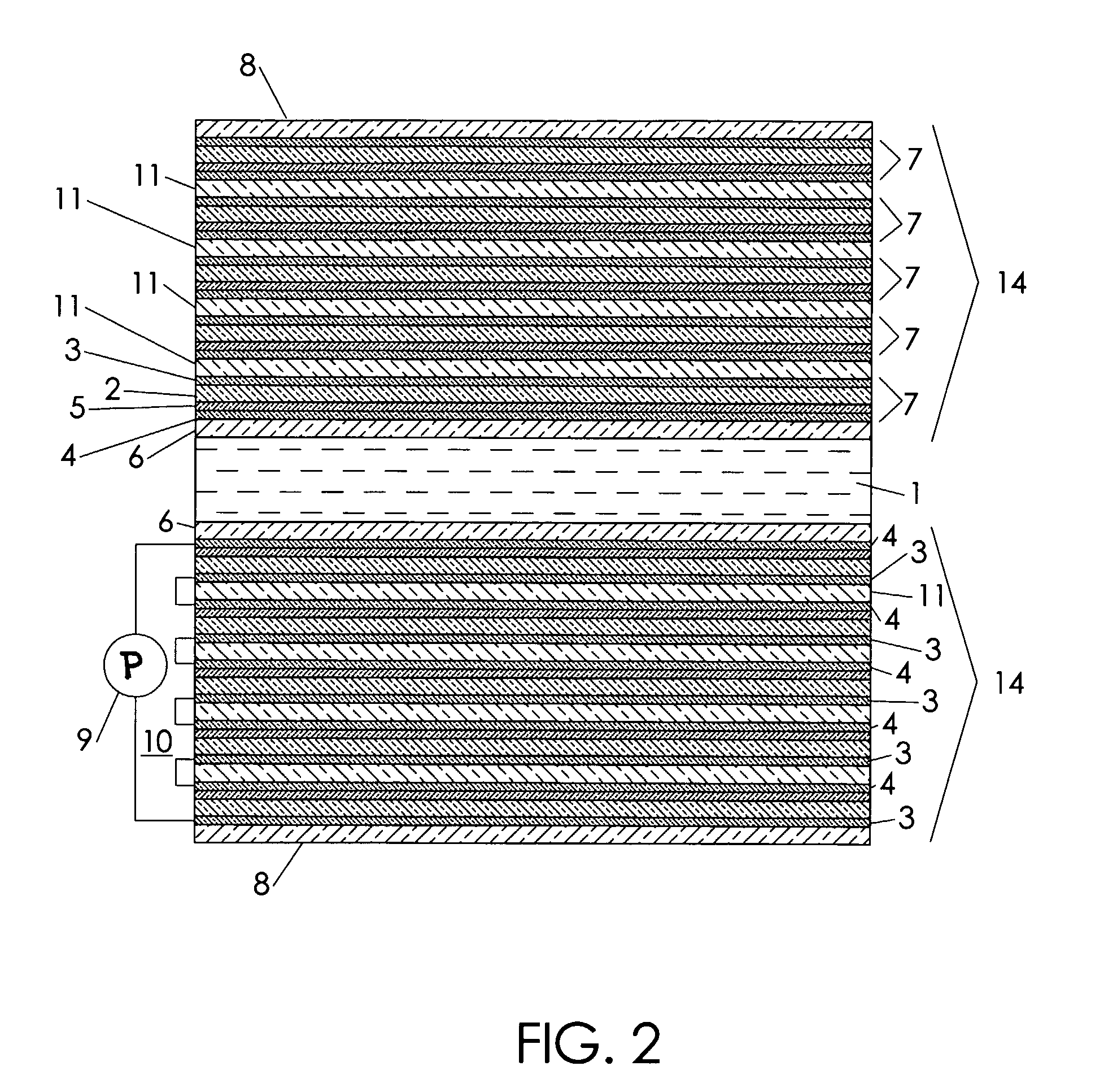
[0019] In a second embodiment, a multitude of the disclosed thin-film electrolytic assemblies are formed into a larger multilayer stack of electrolytic assemblies, so that greater resistance to non-electrolytic gas diffusion may be achieved in the same structure, while still providing mechanical flexibility. An electrolytic stack of this second embodiment is disposed on either side of a relatively thin (<1 mm) flexible material comprising the protected article—such as PET polymer film or organic semiconductor—that contains an oxygen-sensitive component.
[0020] In a third embodiment, the multilayer electrolytic stack is disposed on one side of the thin flexible material, and a passive barrier is disposed on the opposite side of the flexible material. The passive barrier may comprise a transparent polymer-oxide multilayer used in prior art environmental barriers, or it may comprise other barrier structures such as metal layers, etc. The electrolytic stack may be utilized to provide oxygen pumping from the flexible material so as to enable an oxygen density within the flexible material that is below an acceptable maximum. In this way, the disclosed electrolytic stack may be utilized to offset oxygen contamination of the flexible material due to leakage by the passive barrier. In the case that the passive barrier provides good barrier properties, but is opaque, the electrolytic stack may comprise transparent materials for transmitting optical radiation from an organic light emitting diode disposed on or in the flexible material.
[0030] One object of the invention is to provide a multilayer barrier structure that may be economically fabricated on a commercial scale.
[0044] Another object of the invention is to provide a process and method for producing a multilayer barrier structure, wherein a highly defective inorganic layer is impregnated with monomer through a high degree of surface activation.

Problems solved by technology

Such room-temperature oxygen conductivity is normally of little use in real-world applications.

Method used


Image

  • Oxygen Transport Structure
  • Oxygen Transport Structure
  • Oxygen Transport Structure

Examples


Embodiment Construction

[0052] The following description and FIGS. 1-5 of the drawings depict various embodiments of the present invention. The embodiments set forth herein are provided to convey the scope of the invention to those skilled in the art. While the invention will be described in conjunction with the preferred embodiments, various alternative embodiments to the structures and methods illustrated herein may be employed without departing from the principles of the invention described herein.

[0053]FIG. 1 is a sectional side-view of an electrolytic assembly of the invention. The protected article (1) preferably comprises a material that is substantially permeable to oxygen or moisture, the protected article may comprise a substrate including a component that is sensitive to oxygen or moisture, so that preventing oxygen transport to the protected article is desirable. Accordingly, such oxygen-sensitive components may comprise various types of organic light-emitting materials, thin-film transistor (...


PUM

PropertyMeasurementUnit
Temperatureaaaaaaaaaa
Electrical conductivityaaaaaaaaaa
Densityaaaaaaaaaa

Abstract

An oxide-based electrolytic structure and process is disclosed, which is particularly useful for use as an oxygen separation device. The disclosed structures utilize thin film layers to provide the oxygen separation in conjunction with polymer substrate materials. The disclosed devices operate at relatively low temperatures to provide a relatively low flux density (typically 10−10-10−14 g / cm2 sec) of ion conduction, compared to prior art solid oxide electrolytes, whereas substantial oxygen separation is provided over relatively large areas. The disclosed oxygen separation devices are particularly suited for protection of organic-based semiconductors.

Description

RELATED APPLICATIONS [0001] The present application is related to U.S. Provisional Patent application Ser. No. 60 / 636,985 filed Dec. 17, 2004, of which it claims benefit.TECHNICAL FIELD [0002] The invention relates generally to the fields of electrolytic oxide devices, and in particular, of thin film oxygen separation devices; and, more particularly, to such devices utilized with flexible substrates. BACKGROUND ART [0003] Throughout this application, various publications and co-pending patent applications are referenced. In the present disclosure, each of these publications and applications in their entireties are hereby incorporated by reference. [0004] The present disclosure relates to the use of metal-oxide (e.g., “solid oxide”) electrolytic assemblies in relatively low-temperature, flexible, thin-film devices. Solid oxide electrolytic research and development has hither-to been oriented toward the practical uses of such materials; namely, solid-oxide fuel cells, oxygen generatio...

Claims


Application Information

Patent Timeline
IPC IPC(8): C25B1/02B01D50/00C25D17/00H01L51/00
CPCB01D53/326B01D2257/104H01L2251/5338H01L51/5237C01B13/0255H10K2102/311H10K59/8731H10K50/8445
Inventor HILLIARD, DONALD BENNETT
Owner HILLIARD DONALD BENNETT
Learn More