Superconducting Fault-Current Limiting Element and the Process for Producing the Same

a technology of fault-current limiting element and superconducting, which is applied in the direction of superconductor device, superconductor/solid-state device details, emergency protective arrangements for limiting excess voltage/current, etc. it can solve the problem of increasing the volume of expensive insulating substrate, increasing the quantity of generated heat, and increasing the fault-current. problem, to achieve the effect of reducing the inductance of an external shunt resistor, reducing the cost and increasing the resistan

Inactive Publication Date: 2008-01-31
NAT INST OF ADVANCED IND SCI & TECH
View PDF6 Cites 13 Cited by
  • Summary
  • Abstract
  • Description
  • Claims
  • Application Information

AI Technical Summary

Benefits of technology

[0021] In accordance with the inventions described in claim 1 or 2, the superconducting fault-current limiting element having a higher sharing electric field can be produced at low cost.
[0022] In accordance with the invention described in claim 3, since the resistance of the alloy layer can be increased, the superconducting fault-current limiting element having a higher sharing electric field can be realized.
[0023] In accordance with the invention described in claim 4, since the inductance of an external shunt resistor can be reduced, an overcurrent can be easily transferred to the shunt resistor.
[0024] In accordance with the invention descried in claim 5, the alloy having substantially the same composition as that of a target can be easily formed. Good intimate contact with the superconducting thin film can be realized without conducting the subsequent heat treatment, so that a contact resistance between the alloy layer and the superconducting thin film can be reduced.

Problems solved by technology

A serious problem in promoting dereguration in power systems is an increase in the fault-current at the short-circuiting accident due to the connection of new distributed power sources.
However, since the superconducting thin film is expensive, it has been demanded to decrease the area of the superconducting thin film employed as the fault-current limiting element to the utmost, thereby reducing the cost.
However, since the quantity of heat generated by the thin-film current-limiting element during the current-limiting operation can be expressed as P=V2 / R, increase in the sharing electric field leads to an increase in the quantity of generated heat.
However, the latter increases the volume of the expensive insulating substrate and so will lead to cost increase.
However, in actual use, since the thin film with a high critical current density is adopted, there is the problem of a “hot spot” as described in the following paragraph.
However, addition of such metallic shunting layer greatly reduces the electrical resistance of the superconductive path and increases the heat generation during the current-limiting operation.
As a result, in order to acquire the required current-limiting capacity, the element length must be increased and a large quantity of the expensive superconducting thin film must be employed.
This is a serious obstacle to actual use.
However, according to this technique, it is necessary to use a large quantity of a highly thermal conductive ceramic substrate such as aluminum nitride and indium plate.
Since these materials are expensive, there has been a limit in cost reduction.

Method used


Image

  • Superconducting Fault-Current Limiting Element and the Process for Producing the Same
  • Superconducting Fault-Current Limiting Element and the Process for Producing the Same
  • Superconducting Fault-Current Limiting Element and the Process for Producing the Same

Examples


Embodiment Construction

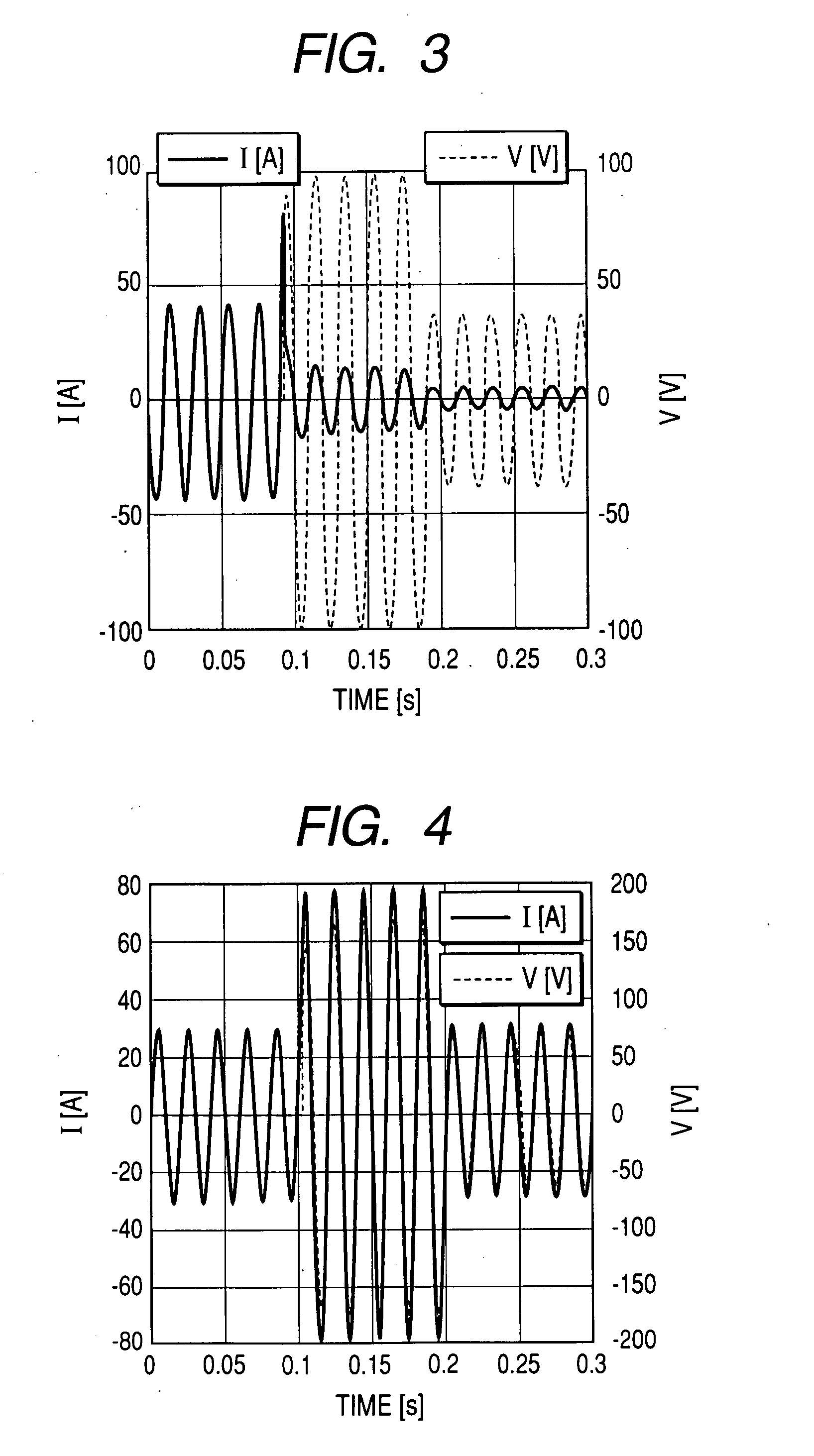
[0036] Referring to FIGS. 1 to 4, an explanation will be given with regard to one embodiment of the invention.

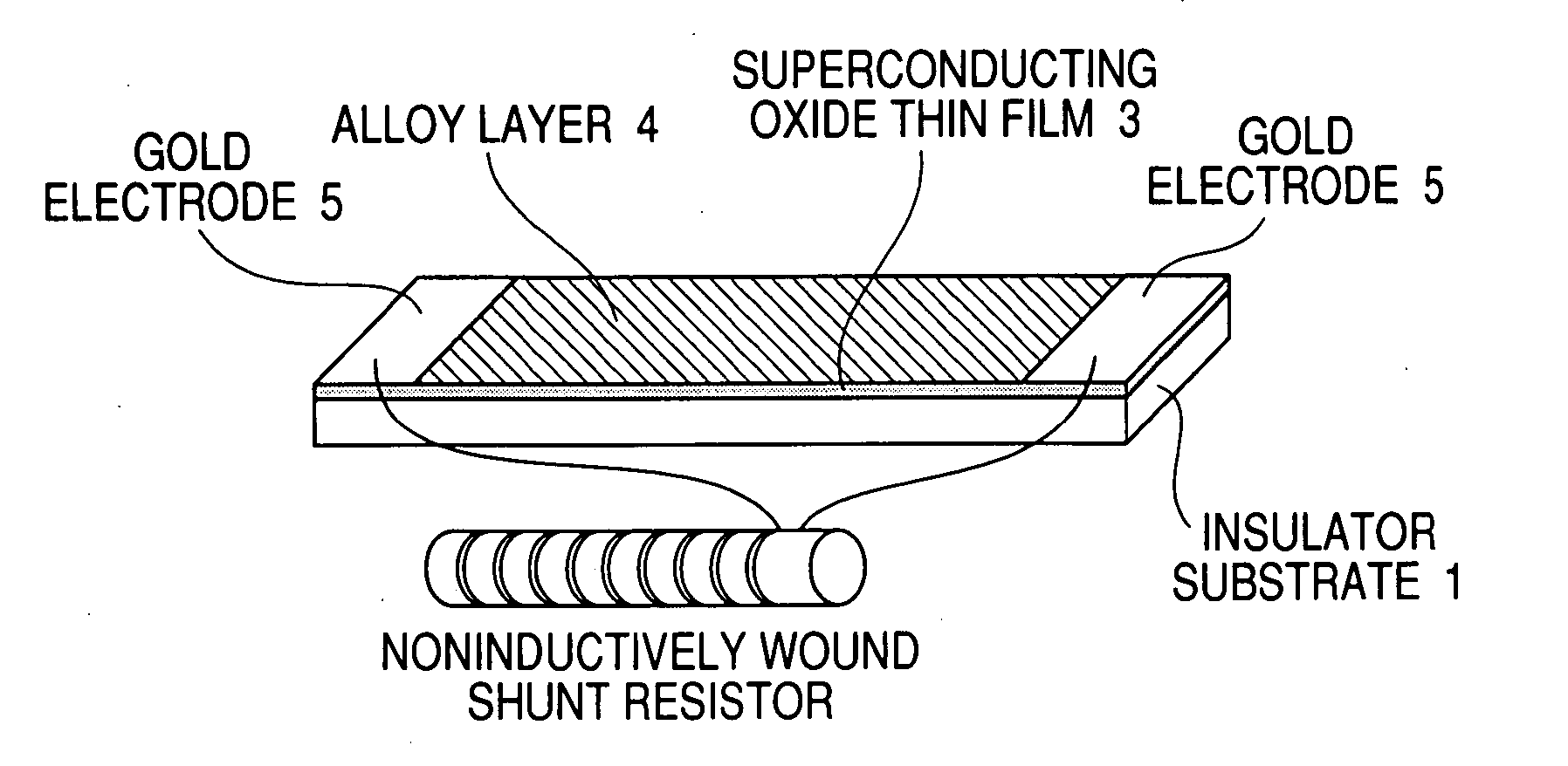
[0037]FIG. 1 is a view showing the construction of a superconducting thin-film fault-current limiting element.

[0038] In FIG. 1, reference numeral 1 denotes an insulator substrate of sapphire or the like; 2 denotes a buffer layer of ceria or the like; 3 denotes a large-area superconducting oxide thin film; and 4 denotes an alloy layer having a predetermined film thickness deposited on the superconducting oxide thin film 3.

[0039] The alloy layer 4 may be a binary alloy composed of gold and silver which is stable in the air and does not react with the superconducting oxide thin film 3. When the alloy layer 4 has the composition of gold and silver mixed by 7 to 82 wt % therewith, the resistivity thereof at room temperature is twice or more as large as that of pure gold. Therefore, the alloy layer having such a composition is favorable in construction of the superconducting th...


PUM

PropertyMeasurementUnit
temperatureaaaaaaaaaa
Fault current limiting propertiesaaaaaaaaaa
sizeaaaaaaaaaa

Abstract

[Problem] To prepare a superconducting fault-current limiting element having a high sharing electric field at low cost.
[Means for Resolution] A superconducting fault-current limiting element including an insulator substrate; a superconductive thin film 3 formed on the insulator substrate; and an alloy layer 4 formed on the superconducting thin film 3, said alloy layer having a room-temperature resistivity higher by twice or more than the room-temperature resistivity of a pure metal, in which, when the superconducting thin film 3 goes into a normal conductive state by an overcurrent, the overcurrent flowing through the superconducting thin film 3 is transferred only to the alloy layer 4.

Description

TECHNICAL FIELD [0001] The present invention relates to a superconducting fault-current limiting element for limiting an overcurrent such as a short-circuiting current flowing through a current path and the process for producing the same. BACKGROUND ART [0002] Although a superconductor permits a large current to pass with no resistance in a superconductive state, when a current larger than a particular value (critical current) passes, it generates an electrical resistance. When the current is further increased, the temperature of the superconductor rises owing to generated heat so that the superconductor goes into a normal conductive state, thereby generating a large electrical resistance. By making the use of such a feature of the superconductor, a superconducting fault-current limiter has been employed which has no resistance during a normal operation condition and generates a large resistance in the short-circuiting accident of an electric power system, thereby suppressing an inc...

Claims


Application Information

Patent Timeline
Patent Type & Authority Applications(United States)
IPC IPC(8): H02H9/08B05D5/12H01B12/06
CPCY10S420/901H10N60/30
Inventor YAMASAKI, HIROFUMIFURUSE, MITSUHO
Owner NAT INST OF ADVANCED IND SCI & TECH
Why Eureka
Try Eureka