
Protective Fiber Optic Union Adapters

a fiber optic union and adapter technology, applied in the field of optical systems, can solve the problems of affecting the performance of the network, so as to reduce the potential for damage, and reduce the loss of insertion

Active Publication Date: 2008-01-24
TELESCENT
View PDF15 Cites 74 Cited by
  • Summary
  • Abstract
  • Description
  • Claims
  • Application Information

AI Technical Summary

Benefits of technology

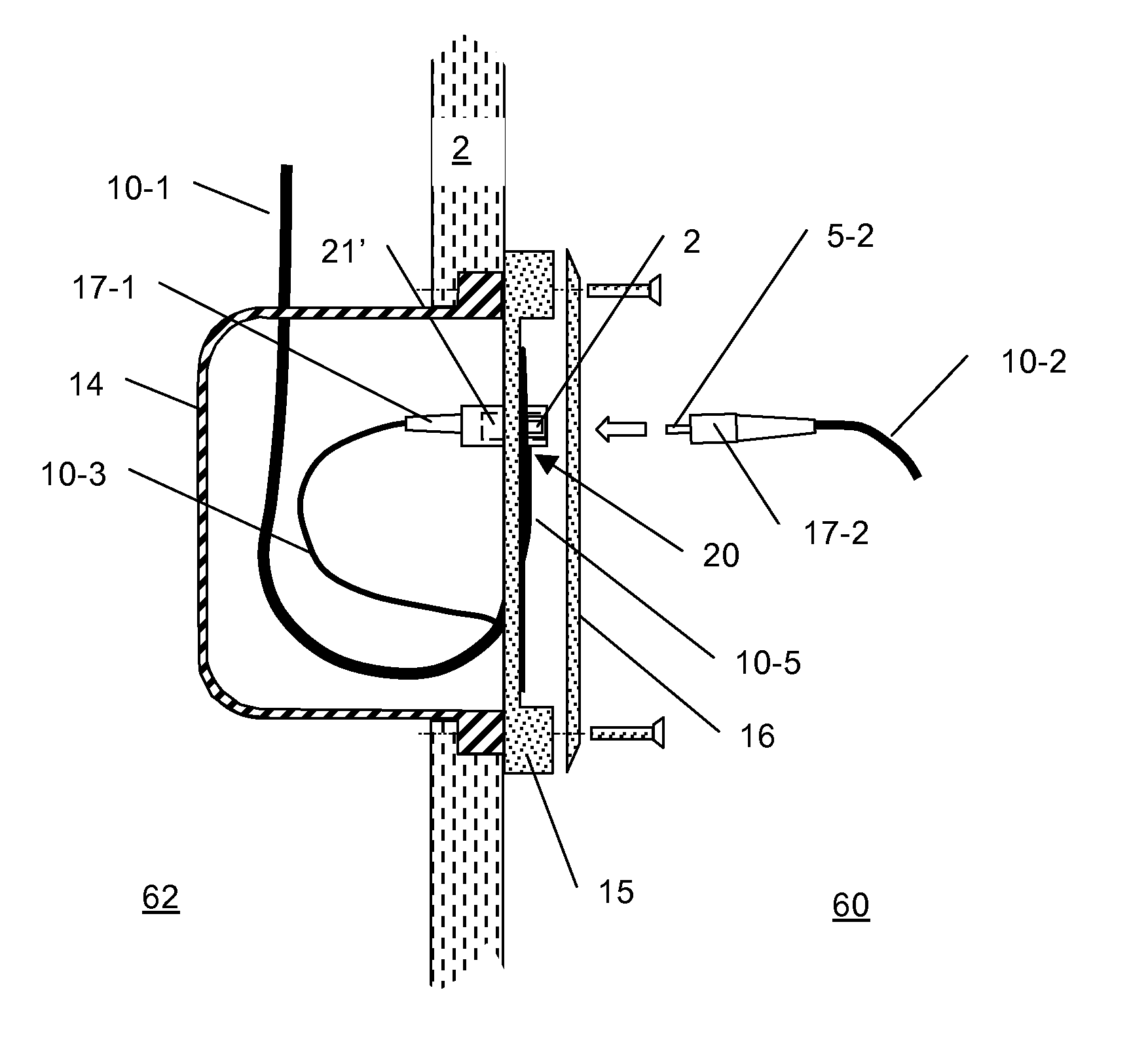
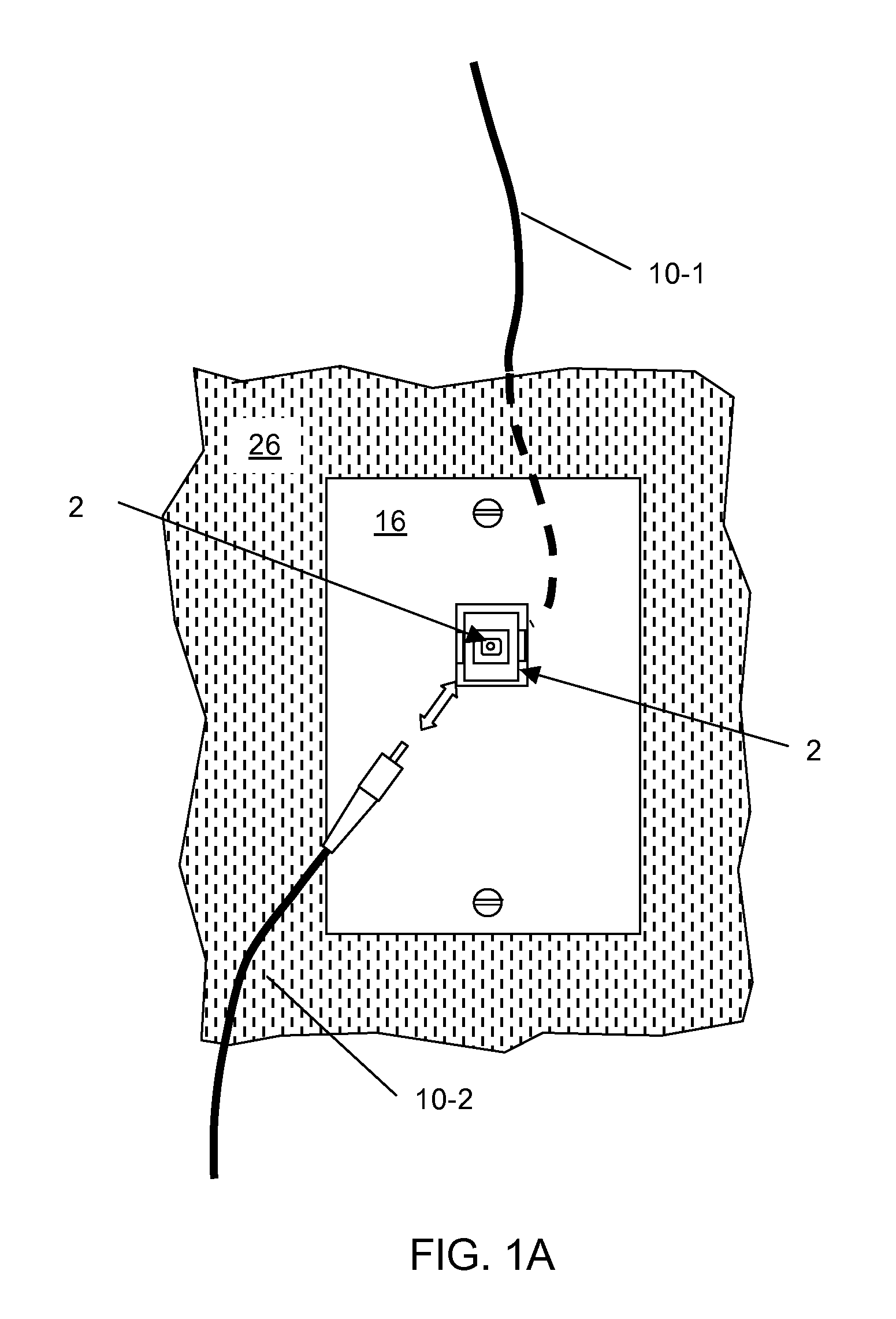
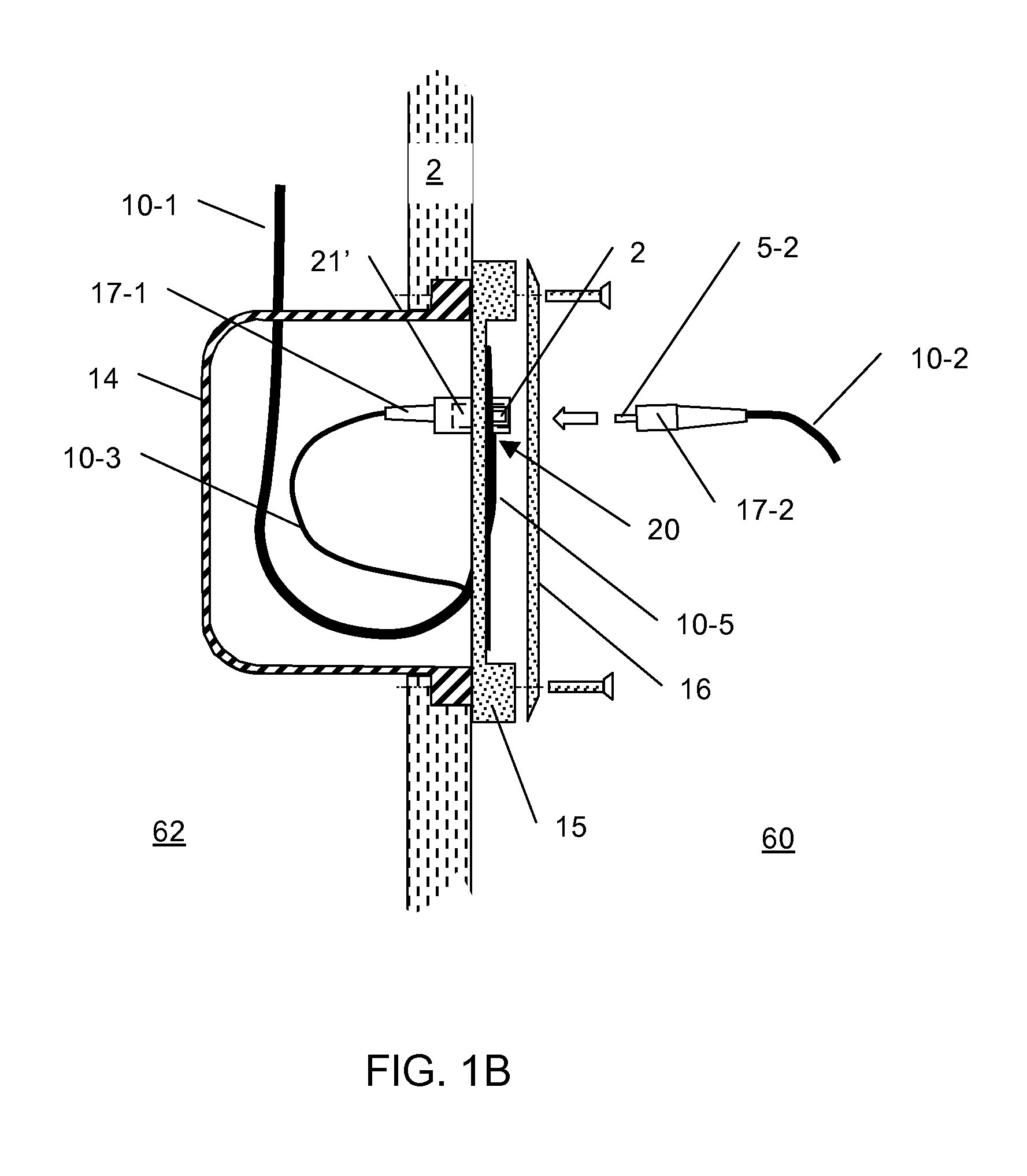
[0024] This invention discloses compact, protective, and sacrificial fiber optic union adapters incorporating an internal adiabatic waveguide core transition section to reconfigurably interconnect two fiber optic cables with low insertion loss and low back reflection. The deployment of these adapters within fiber optic networking systems reduces the potential for damage to “back-side”, or partially inaccessible fiber optic cable spans, thereby minimizing networking downtime and reducing maintenance costs. These adapters include a miniature internal fiber stub element within a precision alignment sleeve to prevent direct physical contact between the polished end faces of connectorized fibers, while providing highly efficient optical coupling between the two mating fiber optic cables through an adiabatic waveguide core transition. The term “adiabatic” refers to the slow variation of waveguide core optical propagation characteristics across the mating fiber interface. The slow variation ensures that the optical signal is not coupled into other forward, backward, or scattering optical modes, all of which contribute to optical loss downstream of the union adapter and backreflections upstream of the union adapter. The internal fiber stub element comprises length(s) of single mode or multi-mode fiber(s) bonded within a precision ferrule and precisely polished on opposite end faces. The optical fiber and polished end face characteristics are selected to be nominally identical to the connectorized fibers attached thereto.

Problems solved by technology

The polished ferrule contact areas are highly susceptible to scratching caused by repeated mating and demating cycles in the presence of contaminants trapped on or in the vicinity of the contact area.
Surface damage to the fiber endface in the vicinity of the optical fiber's core degrades optical performance.
In particular, the increased excess loss and reduced return loss can seriously compromise the network's performance.
With broadcast-type access networks, in which the optical signal is power split between as many as thirty-two users, the optical power budget of the network has low margin and the impact of such damage is particularly significant.
This problem is exacerbated by the fact that a single contaminated or damaged fiber / ferrule, if connected to other clean and undamaged fiber terminations, can degrade these other fiber terminations and propagate connector damage throughout the network.
In this decentralized architecture, the cost to diagnose and repair damaged terminations increases considerably depending on the physical location of the termination within the network.
For instance, damage to an inaccessible connectorized drop cable originating from within a customer's wall or damage at the connector interface of a populated, high-density fiber patch panel requires a costly service call and repair by an experienced technician.
Typically, the ends of the fiber optic drop cable within the customer's premises are terminated using highly specialized and costly fiber optic termination equipment.
Fiber optic cable is particularly susceptible to cracking due to excessive bends and polished fiber optic terminations are susceptible to scratching if contacted with dirty and contaminated connectors.
Repair and debugging requires skilled fiber optic technicians, adding significant cost and overhead to maintain the network.
As a consequence, present day fiber optic systems lack the robustness commonly found in electronic networking systems.
However, these approaches do not prevent a damaged or contaminated connector ferrule from damaging the mating connector.
This adapter produces significant insertion loss (>=5 dB) since it is designed to produce attenuation.
These attenuators interrupt the longitudinal continuity of the central waveguide cores attached to either side of the attenuator housing and thereby introduce a significant amount of loss and optical backreflection.

Method used


Image

  • Protective Fiber Optic Union Adapters
  • Protective Fiber Optic Union Adapters
  • Protective Fiber Optic Union Adapters

Examples


example

Optical Signal Processor with Replaceable Receptacles

[0042] In a particular example, the male-to-female isolating adapters are used to isolate the fiber optic ports of an optical signal processor. More specifically, the optical signal processor may be in the form of a duplex fiber optic transceiver module, an example of which is illustrated in FIGS. 7A and 7B. This module may be transmit optical Ethernet-formated data at rates up to 10 Gbit / sec and include electrical signal conversion or communication via connector 34. The transceiver module 33 is packaged within a housing 32 and includes integrated duplex, female-type fiber optic receptacles 31. In FIG. 7 these receptacles 31 are of the SC-UPC type with either multi-mode or single mode fiber interfaces, for example, and with alignment channels 35. Alternate receptacle types include LC, ST and MTRJ. Damage to the internal fiber interfaces within receptacle 31 is difficult or impractical to repair. To protect this interface from dam...


PUM


Abstract

Devices to enhance the reliability of optical networks and to reduce the cost of repair are disclosed in this invention. In particular, compact and inexpensive fiber optic union adapters with built-in protective isolation prevent the transfer of damage from one connectorized fiber optic cable to another. The fiber optic union includes a split sleeve with an interior channel and a fiber stub centrally located within the interior channel. The fiber stub makes direct optical contact with the cable endfaces to enable efficient optical transmission between interconnected cables while providing a low loss, low back reflection adiabatic transition between the waveguide cores of the two cables.

Description

REFERENCE TO RELATED APPLICATIONS [0001] This application is a continuation-in-part of U.S. patent application Ser. No. 11 / 307,688, filed on Feb. 17, 2006 and entitled “Isolated Fiber Optic Union Adapters”.FIELD OF THE INVENTION [0002] This invention relates to optical systems using fiber optic cables to transmit illumination and / or signals, and more particularly, to devices enabling low insertion loss and low back reflection connections between fiber optic cables while also preventing the propagation of connector end face damage between cables. BACKGROUND OF THE INVENTION [0003] Fiber optic cables are terminated with polished connectors that interchangeably interconnect with low optical insertion loss to other patchcords or fiber optic devices having compatible connectors. These connectors include an optical fiber, one end of which is stripped to expose the bare glass and bonded within a precision, close tolerance hole of a ferrule. The fiber and ferrule end faces are made co-plana...

Claims


Application Information

Patent Timeline
Patent Type & Authority Applications(United States)
IPC IPC(8): G02B6/38
CPCG02B6/3825G02B6/3897G02B6/3846G02B6/3877
Inventor KEWITSCH, ANTHONY S.
Owner TELESCENT
Learn More