Liquid crystal display device and a manufacturing method of the same
a technology of liquid crystal display and manufacturing method, which is applied in the direction of static indicating devices, operating means/releasing devices of valves, instruments, etc., can solve problems affecting quality or yield, and achieve the effect of preventing an increase in the number of photo-etching processes
- Summary
- Abstract
- Description
- Claims
- Application Information
AI Technical Summary
Benefits of technology
Problems solved by technology
Method used
Image
Examples
embodiment 1
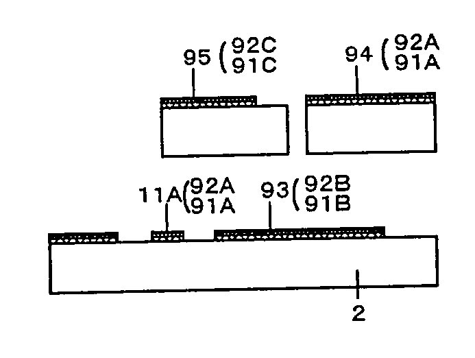
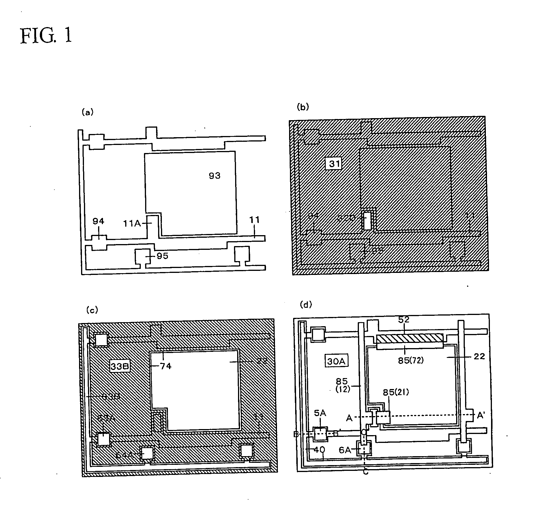
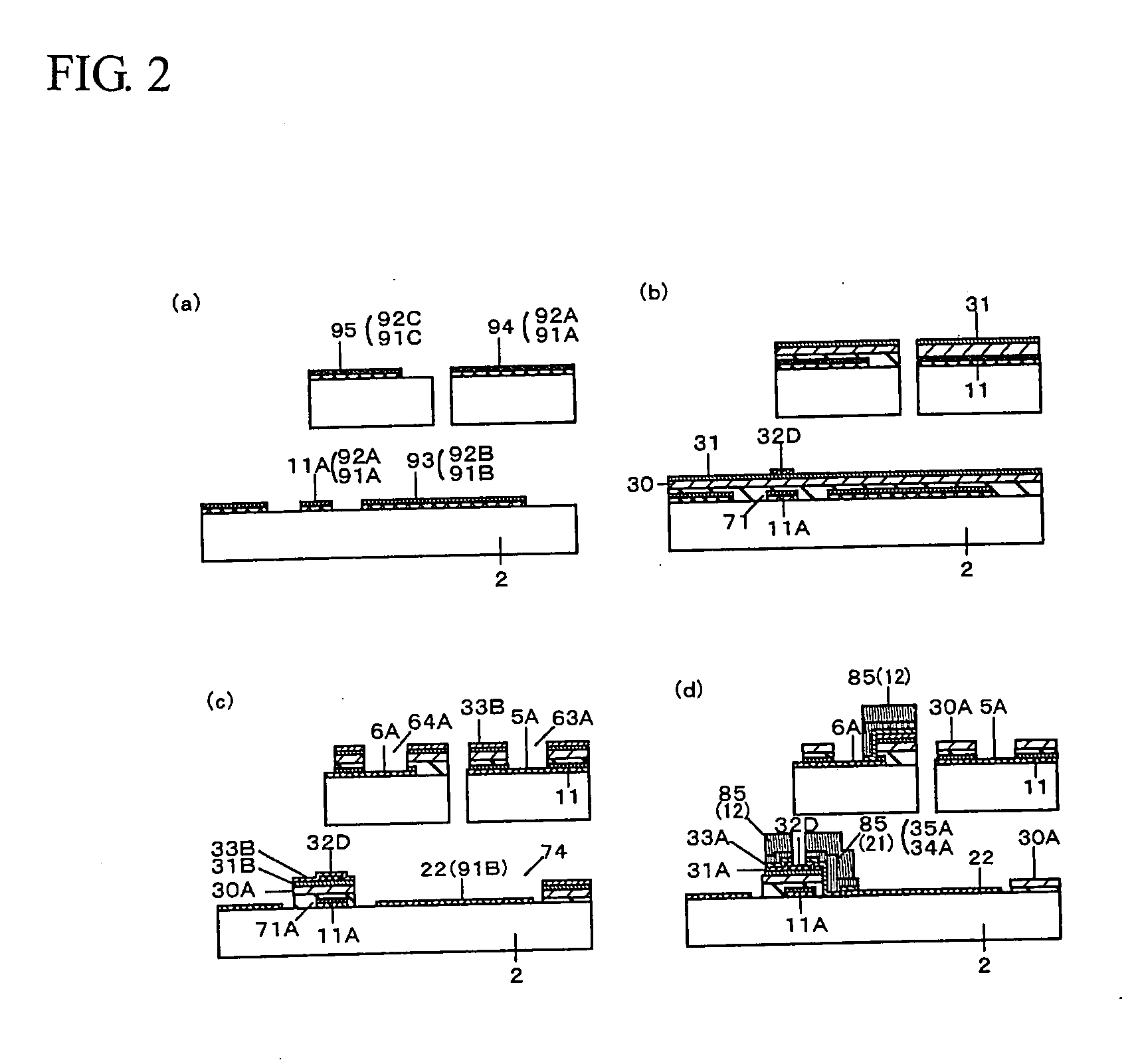
[0080] In Embodiment 1, first, an SPT or other vacuum film depositing equipment is used to deposit ITO, for example, as a transparent conductive layer 91 about 0.1 to 0.2 μm thick and a first metal layer 92 about 0.1 to 0.3 μm thick on the main surface of glass substrate 2. Then, scan lines 11 doubling as gate electrodes 11A comprising a laminate made of a transparent conductive layer 91A and first metal layer 92A and pseudo-electrode terminals 94 of the scan lines; pseudo-pixel electrodes 93 comprising a laminate made of a transparent conductive layer 91B and a first metal layer 92B; and pseudo-electrode terminals 95 of signal lines comprising a laminate made of a transparent conductive layer 91C and a first metal layer 92C, are selectively formed using photosensitive resin patterns using micro-fabrication technology as shown in FIG. 1 (a) and FIG. (2). A metal with a high melting point such as Cr, Ta, or Mo, for example, or an alloy or a silicide thereof may be selected for the fi...
embodiment 2
[0087] In Embodiment 2, the process proceeds nearly identically to that in Embodiment 1 up until the contact formation process as shown in FIG. 3(c) and FIG. 4(c). Because of the reason described below, the pseudo-electrode terminal and 95 of the signal line and are not necessarily required. A thin film layer 34 of Ti, Ta, or the like, for example, is deposited about 0.1 μm thick as a heat-resistant metal layer, and then an Al thin film layer 35 is subsequently deposited as a low-resistance wire layer about 0.3 μm thick using an SPT or other vacuum film depositing equipment in the source-drain wires formation process. Then, the source-drain wire materials comprising these two thin film layers, the second amorphous silicon layer 33B, and the first amorphous silicon layer 31B are successively etched using the photosensitive organic insulating layer patterns 86A and 86B, using micro-fabrication technology to expose the protective insulating layers 32D and the gate insulating layer 30A ...
embodiment 3
[0094] In Embodiment 3, a process nearly identical to that in Embodiment 2 is carried out until where openings 63A are formed on part of the scan lines 11 outside the image display area to expose part of the scan lines 11 as shown in FIG. 5(c) and FIG. 6(c). Continuing, a thin film layer 34 of Ti, Ta, or the like, for example, is deposited about 0.1 μm thick as an anodizable heat-resistant metal layer, and then an Al thin film layer 35 is similarly deposited as an anodizable low-resistance wire layer about 0.3 μm thick using an SPT or other vacuum film depositing equipment in the source-drain wire formation process. Then, source-drain wire materials comprising these two thin film layers, the second amorphous silicon layer 33B, and the first amorphous silicon layer 31B are successively etched using the photosensitive resin patterns 87A and 87B using micro-fabrication technology to expose the protective insulating layers 32D and the gate insulating layer 30A. The drain electrodes 21 o...
PUM
| Property | Measurement | Unit |
|---|---|---|
| photosensitive | aaaaa | aaaaa |
| length | aaaaa | aaaaa |
| dimension | aaaaa | aaaaa |
Abstract
Description
Claims
Application Information
 - R&D
- Intellectual Property
- Life Sciences
- Materials
- Tech Scout
- Unparalleled Data Quality
- Higher Quality Content
- 60% Fewer Hallucinations
Browse by: Latest US Patents, China's latest patents, Technical Efficacy Thesaurus, Application Domain, Technology Topic, Popular Technical Reports.
© 2025 PatSnap. All rights reserved.Legal|Privacy policy|Modern Slavery Act Transparency Statement|Sitemap|About US| Contact US: help@patsnap.com


